Download
1 / 33
330 likes | 554 Views
Team 5 Critical Design Review. Trent Lobdell Ross May Maria Mullins Christian Naylor Eamonn Needler Charles Reyzer James Roesch Charles Stangle Nick White. Outline. Mission Requirements Team Design Aerodynamics Dynamics & Control Propulsion Structures / Landing Gear

E N D
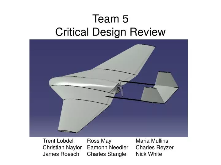
Team 5Critical Design Review Trent Lobdell Ross May Maria Mullins Christian Naylor Eamonn Needler Charles Reyzer James Roesch Charles Stangle Nick White
Outline • Mission Requirements • Team Design • Aerodynamics • Dynamics & Control • Propulsion • Structures / Landing Gear • Prediction of Vehicle Performance • Remaining Design Problems AAE 451 – Team 5
Requirements • Design Requirements & Objectives • Take-Off and landing distance: 100 ft* • Take-Off with minimum climb angle: 20° • Endurance: 15 min* • Typical descent angle of: 5.5° • Stall Speed: 20 ft/s • Loiter Speed: 28 ft/s* • Minimum Turn speed: 23.33 ft/s* • Turn Radius: 35 ft* • Operating Altitude: 18 ft* • Operational Airspace: 360x150 ft *Changed Requirements from Mission Specification AAE 451 – Team 5
Design Features • Features / Unique Aspects • Stealth Theme • Twin Booms • Pusher Prop • Multi-Sweep Wing Predicted Weight: 0.84 lbf AAE 451 – Team 5
Design Properties Wing Horizontal Tail Overall Aircraft Vertical Tail Fuselage AAE 451 – Team 5
Design - Dimensions AAE 451 – Team 5
Aerodynamics - Airfoils • Low Re Number • 91903 (Stall) - 128660 (Cruise) • Wing • Eppler E212 • Tail • Eppler E169 Horizontal Tail • NACA 0010 Vertical Tail NASG: http://www.nasg.com/afdb/search-airfoil-e.phtml UIUC: http://www.aae.uiuc.edu/m-selig/ads/coord_database.html AAE 451 – Team 5
Aerodynamics – Geometry • Defined Sweep Angles (Λ) • Defined taper ratio (λ) of 1st segment • Defined Span Ratio of 2 segments • Adjust to balance • Style • Aspect Ratio • Tip Chord feasibility AAE 451 – Team 5
Aerodynamics - Lift Sweep Corrected Hembold Equation1 Lift Coefficients vs. α Prandtl Lifting Line Theory1 CL and Cl CLmax (Hembold): 0.74 Max Lift (Hembold): 1.10 lbf α (deg) 1 Anderson, J.D., Fundamentals of Aerodynamics, New York, 2001, pp 351-416 AAE 451 – Team 5
Aerodynamics - Drag • Parasite Drag Buildup Sref = reference area [ft2] Cf = skin friction coefficient K = form factor Q = interference factor AAE 451 – Team 5
Aerodynamics – L/D • L/Dmax=13.21 • Loiter at α=.71°,4.46° • Loiter at 0.866*L/Dmax2 • Wing Incidence: 3° • Tail Incidence: -7.3° L/D vs. α L/D=4.7 L/D α (deg) 2 Raymer, D.P., Aircraft Design: A Conceptual Approach, Virginia, 1999, pp 27 AAE 451 – Team 5
Class 2 Tail Sizing (X-plot) AAE 451 – Team 5
Trim Diagram AAE 451 – Team 5
Control Surface Sizing • Aileron size / dimension: • Area:0.04 ft2 • Length: 0.63 ft • Root Chord: 0.08 ft • Tip Chord: 0.05 ft • Elevator size / dimension: • Area: 0.10 ft2 • Span: 0.50 ft • Chord: 0.21 ft • Rudder size / dimension: • Area: 0.02 ft2 • Base 1: 0.04 ft • Base 2: 0.15 ft • Height: 0.19 ft AAE 451 – Team 5
Class 2 Vertical Tail Sizing (X-plot) 0.218 ft2 AAE 451 – Team 5
Feedback ControllerPitch Rate Feedback to Elevator AAE 451 – Team 5
Feedback Controller • Damping Ratio w/o Feedback = 0.74 • Desired Damping Ratio = 0.35 – 1.3 • We chose a Damping Ratio = 0.95 • Feedback Gain Required = 0.07 AAE 451 – Team 5
Propeller Take-Off Characteristics AAE 451 – Team 5
Propeller Plots – 6 inch prop Loiter Take-Off CT = 0.025 CP = 0.023 η = .83 CT = 0.076 CP = 0.042 η = .61 AAE 451 – Team 5
Motor Selection - Graupner Speed 400 6V(Direct Drive) Characteristics AAE 451 – Team 5
Battery & Speed Controller Selection • Thunder Power 3 Cell Li-Po • Rated for 12-15 Amps • 2100 mAh • Allows for extended endurance as specified in the DR&O • 4.6 oz. • JETI 12 Amp Microprocessor Motor Controller • For 2-3 Cell LiPo • Weight = 0.53 oz. • 1x0.75x0.3 in. AAE 451 – Team 5
Landing Gear • Parameters • θ = 30° • Material = Al • Ngear = 3 (Gen. Av.) • Main gear (2) • Single beam, t = 0.0017 ft • Stroke = 0.0458 ft • Weight = 0.0018 lbf • 30° angle for lateral stability • 20° in front of CG for longitudinal stability • Absorb impact • Gear deform instead of break • Easy to change • TailGear (2) • 18 gauge steel wire • Prevent prop and tail strike • Gear deform instead of break AAE 451 – Team 5
Structures - CG AAE 451 – Team 5
Structures - Load Analysis • Structural loads from code – basic equations used • τ max = 2.40 lbf/ft2 • Mroot = 0.26 ft-lbf • σmax = 0.0048 lbf/ft2 • Deflections • δy = 9.1e-11 ft • δΦ = 1.1e-4 degrees AAE 451 – Team 5
Structures - Load Analysis • Torsion Loads • T = 0.1 ft-lbf. at high maneuver • Failure of wing (most likely due to buckling) occurs at • ncr = 38 or at σcr = 32 psf. AAE 451 – Team 5
Scheduled Tests • Drop Test • Height of 2.5 ft • Tests landing gear and crash survivability • Wing Load Test • Test maximum load of wing • Flight Test • Propeller test • Feedback gain test • Control surface test AAE 451 – Team 5
Strength Testing Failure at 26 lbf AAE 451 – Team 5
Strength Testing Failure due to buckling AAE 451 – Team 5
Manufacturing • Wing/fuselage and tails milled using CNC • Wet lay-up with 0.6 oz. bidirectional s-glass • Holes cut and tapped for component placement • Epoxy bonding of tails and booms • Mechanical attachment of landing gear, motor, etc. AAE 451 – Team 5
Manufacturing - Booms • Circular holes cut for boom insertion • Foam is bonded inside and out to tube • Boom pinned into place with wire AAE 451 – Team 5
Overall Schedule • To be accomplished before 1st flight • Order parts – March 10 • Build prototype wing – March 11 • Test prototype strength – March 22 • CDR – March 24 • CNC Parts – by March 28 • Fiberglass Parts – by April 3 • Build – by April 7 • Test and modify – until flight date AAE 451 – Team 5
Predicted Flight Performance • Max. Turning Radius: 35 ft (DR&O) • Bank Angle: 34.82° • Turn Rate: 0.8 rad/s • Min. Turning Radius: 10.92 ft (Limit) • Bank Angle: 65.85° • Turn Rate: 2.57 rad/s • Maximum Climb Angle: 26.77° • Take-Off Distance: 16.29 ft • Landing Distance: 22.48 ft AAE 451 – Team 5
Current Issues • Propeller air flow • Engine heating • Manufacturability • Boom attachments • CG movement AAE 451 – Team 5