Download
1 / 20
220 likes | 394 Views
Team Supersonic Rafael Ramirez Derek Schell Ernest Tom Christopher Walker. Stirling engine. OVERVIEW. Initial Customer Design/Acoustic-Rafael Thermodynamic Model-Chris Construction of Artifact-Derek Testing-Tom Improvements-Tom Reflection-Derek. Initial Customer Design/Acoustic.

E N D
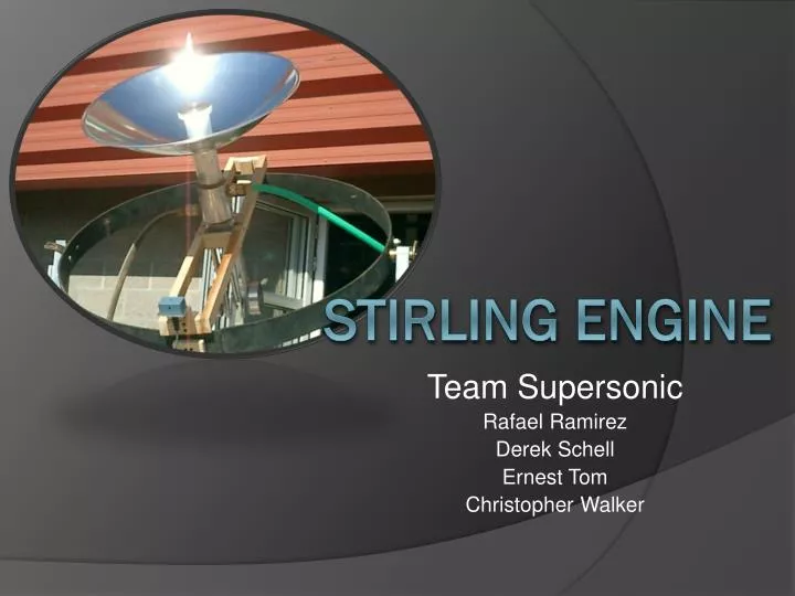
Team Supersonic Rafael Ramirez Derek Schell Ernest Tom Christopher Walker Stirling engine
OVERVIEW • Initial Customer Design/Acoustic-Rafael • Thermodynamic Model-Chris • Construction of Artifact-Derek • Testing-Tom • Improvements-Tom • Reflection-Derek
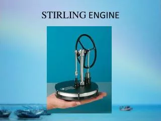
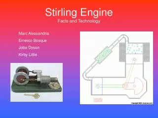
Initial Customer Design/Acoustic Our initial customer design was Thermo Acoustics which is the science of generating or amplifying sound waves using heat. Our team has reconsidered the Thermo Acoustic Project due to limited time and resources .We decided on moving forth a different direction with a Beta Stirling Engine. Reasons: • A Beta Stirling engine seemed to be more feasible than a thermo acoustic engine when it came down to our constraints. • A beta stirling engine modeling and design were fairly similar to thermo acoustics, so all of our progress wasn’t lost. • Out of the major types of stirling engines we chose a beta due to single power piston arranged within the same cylinder on the same shaft as a displacer piston simplifying our design and making us meet our constraints. • Since a beta stirling engine follows a stirling cyclic compression and expansion of air, our modeling followed four processes discussed in Thermo Fluids class
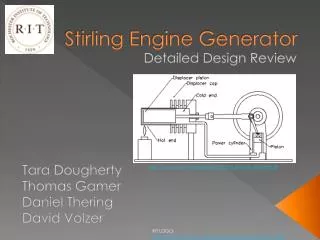
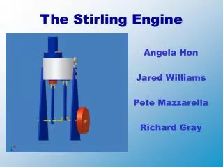
Stirling Engine Components: • Our solar device consists of five components: a dish, heating plate, beta engine, cooling jacket, and a flywheel
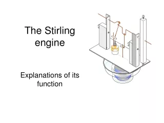
Thermodynamic Model • Stirling Cycle • 1-2: Isothermal Expansion • 2-3: Isochoric Heat Removal • 3-4: Isothermal Compression • 4-1: Isochoric Heat Addition • Initial Condition • 4-1: Isochoric Heat Addition • STP -> 1-2 of the cycle
Thermodynamic Model • Beta-type Stirling Engine/Cycle • 1-2: Isothermal Expansion • 2-3: Isochoric Heat Removal • 3-4: Isothermal Compression • 4-1: Isochoric Heat Addition
Thermodynamic Model • Initial State
Thermodynamic Model • Cycle States
Thermodynamic Model • P-v Diagram 13 W
Thermodynamic Model • Flywheel • KE = ½ I ω² • I = mr² • From work output, and size limit of flywheel due to material on hand and solving for ω • ~22,000 rev/min • Designed for 250 rev/min • System will require a matched load or a brake to operate continuously
Thermodynamic Model • Output
Construction of Artifact • Solidworks Model Developed • Tweaked Model due to materials available • All 6061 Aluminum
Assembled using small ball bearings to reduce friction Attached to purchased parabolic reflector Adjusted to achieve optimal focal length
Attached to Solar Tracker Water Flow Attached
Testing • Ernest • What do you have working? How do you know it works? How have you documented that it works? • How we ran out of time– final assembly issues
Improvements • Ernest • A plan for any future actions necessary to complete the project successfully
Reflection • Much less structured than other projects • More freedom in design and creation of the prototype • More time to model prior to construction • More instruction on the topic of the semester prior to starting the design • More specific constraints • Teams based on scheduling • Required more individual team organization