Download
1 / 77
1.41k likes | 2.2k Views
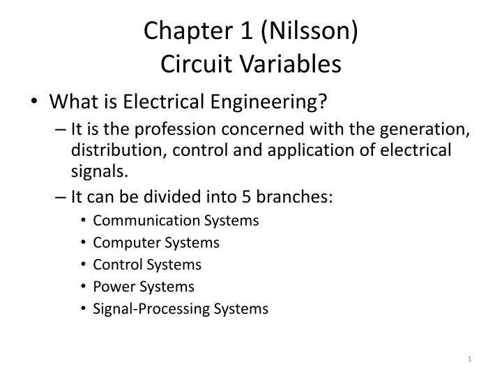
Chapter 1 (Nilsson) Circuit Variables. What is Electrical Engineering? It is the profession concerned with the generation, distribution, control and application of electrical signals. It can be divided into 5 branches: Communication Systems Computer Systems Control Systems Power Systems

E N D
Chapter 1 (Nilsson)Circuit Variables • What is Electrical Engineering? • It is the profession concerned with the generation, distribution, control and application of electrical signals. • It can be divided into 5 branches: • Communication Systems • Computer Systems • Control Systems • Power Systems • Signal-Processing Systems
1. Communication System • These are electrical systems that generate, transmit and distribute information. This information may be audio(sound) or video (picture). Example is a telephone system shown below.
Computer Systems • Ranges from pocket calculators to personal computers to super computers. These systems contain chips (Integrated circuits) which house millions of electrical components.
Control Systems • Include the electrical systems that control equipment or physical variables. Like the control of temperature and pressure in an oil refinery, autopilots in plans and robots.
Power Systems • Generates and distributes electric power.
Signal Processing Systems • They transform electric signal and the information in them into a more suitable form. Example is CT scan which transforms the signal generated by an X-ray machine into an image as shown.
The branches of electrical engineering are not separable. They interact with each other as in an airplane, or robot system.
Electric Circuit • An Electric circuit is a mathematical model that approximates the behavior of an actual electrical system. • Each of the 5 branches (systems) of electrical engineering may be represented by an electric circuit. • From now on, an electric circuit means model of a system.
The International Systems of Units (SI) • It is used by engineers in all disciplines, electrical, mechanical, civil, …
Some quantities are either too small or too large. So we use prefixes.
Electric Charge • An atom consists of negatively charged electrons and positively charged nucleus. The number of positive charges is equal to the number of negative charges. Hence, under equilibrium, the atom is neutral. • Under the effect of temperature, light, or electric field (from battery), an electron may leave the atom and become free electron. The remaining atom becomes a positive charge (called cation) , and the electron represents a negative charge. • The unit of charge is Coulomb (C ). • The symbol of charge is q. • The charge of a single electron is
Oxygen atom in isolation The free electron is responsible for the conduction of current.
Voltage • The voltage results from the separation of charge. • The voltage difference between any two pints is defined as the energy (or work) needed to move one coulomb of charge between these two points, • The voltage of a battery (or voltage source) is 5V means that 5 Joules are needed to move 1C from the negative terminal to the positive terminal of the battery. • If the work (or energy) is denoted by w, and the voltage v, then • The unit of voltage is Joules/Coulomb or volt.
Current • The current results from the movement of charge. • The current is defined as the amount of charge passing through a given wire cross section in 1 second. • If time is denoted by t and charge by q, then • The current i has units of Coulomb/second or Ampere • The current in a wire is 5A means 5 Coulombs are passing through this wire cross section in 1 second.
There are two types of current: • Conventional Current : It is a hypothetical current the results from the movement of positive charge. • and Electronic Current: It results from the movement of negative charge. • Electrical Engineers agreed to take the conventional current as the default current. So when we say current, we mean conventional current, and when we draw an arrow in an electric circuit, it means the direction of conventional current.
Example 2.1 No charge exists at the upper terminal of the element in the above figure for t<0. At t=0, 5A current begins to flow into the upper terminal. Derive the expression for the charge accumulation at the upper terminal of the element for t>0. If the current is stopped after 10 seconds, how much charge has accumulated at the upper terminal? Solution: a) C b) q(10)=50 C
Example 2.2 If charge entering the element in previous example is find the current. Solution: A
Power and Energy • Power is denoted by p • Energy is denoted by w • Power is the energy absorbed or delivered in 1 second. • Power is also defined as the time rate of delivering or absorbing energy. • Power has units of J/s or Watt
It can be easily shown that p is also given by: Sign Convention of Power: Power delivered to load=power absorbed by load= vi Power delivered by load=vi
P in above figure is power delivered to load or power absorbed by load
Example 2.3 If v=0 for t<0, and v= KV for t>0 also i=0 for t<0, and i= A for t>0 Calculate the power supplied to the element at 1 ms. Calculate the total energy in (J) delivered to the circuit element. Solution: P=vi Hence, for t<0 KW for t>0 W b) J
Balancing Power • The low of conservation energy states that energy cannot be created or destroyed. • As a results, in any electric circuit, the sum of powers absorbed or delivered by all elements should be zero By all elements in a circuit
Example 2.4 • In the circuit shown above, the currents and voltages are given in table below. Are the numbers in the table correct?
Solution: Let us check if the power is balanced by finding the power absorbed by each element (or the power delivered to each element)
The power is not balanced, therefore, the numbers for the currents and voltages in the table are wrong
Chapter 2 (Nilsson)Circuit Elements • There are 5 basic elements in an electric circuit: Voltage sources, Current Sources, Resistors, Inductors, and Capacitors. • Voltage and Current Sources: • An electrical source is a device capable of converting nonelectric energy to electric energy and vice versa. • Example: A discharging battery converts chemical energy to electrical energy • Example: A charging battery converts electrical energy to chemical energy.
A dynamo is a machine that converts mechanical energy (from rotation) to electrical energy. It is therefore called “Generator”. • We will only be concerned with ideal sources now. Practical sources will be studies later. • There are two types of ideal electrical sources: • 1. Ideal Independent sources, and 2. Ideal dependent (controlled) sources.
1. Ideal Independent Sources • These are two types: Ideal Independent voltage sources and Ideal Independent current Sources. • An ideal (independent) voltage source is a circuit element that maintains a fixed voltage between its terminals regardless of the current flowing in these terminals. • An ideal (independent) current source is a circuit element that maintains a fixed current through its terminals regardless of the voltage across these terminals.
Figure : The circuit symbols for (a) an ideal independent voltage source and (b) an ideal independent current source.
2. Ideal Dependent (or controlled) Sources • These are two types: Ideal dependent voltage sources and Ideal dependent current Sources. • An Ideal dependent voltage source (or called controlled voltage source) has its voltage controlled or dependent on another voltage or current that exists somewhere in the circuit. • An Ideal dependent current source (or called controlled current source) has its current controlled or dependent on another voltage or current that exists somewhere in the circuit.
Figure 2.2 The circuit symbols for (a) an ideal dependent voltage-controlled voltage source, (b) an ideal dependent current-controlled voltage source, (c) an ideal dependent voltage-controlled current source, and (d) an ideal dependent current-controlled current source.
Example 2.5 Using the definitions of the ideal independent voltage and current sources, state which interconnections in this figure are permissible and which violate the constraints imposed by the ideal sources.
Solution: • This connection is permissible (valid) because the two ideal voltage sources are connected in parallel and have the same voltage. • This connection is permissible (valid) because the two ideal current sources are connected in series in this circuit and have the same current. • This connection is not permissible (not valid) because the two ideal voltage sources are connected in parallel and do not have the same voltage. • This connection is not permissible (not valid) because the two ideal current sources are connected in series and do not have the same current. • This connection is permissible (valid) because the voltage source will supply 10 V regardless of the current and the current source supplies 5 A regardless of the voltage.
Example 2.6 Using the definitions of the ideal independent and dependent sources, state which interconnections in this figure are permissible and which violate the constraints imposed by the ideal sources.
Solution: • This connection is not permissible (not valid) because the dependent voltage source (vs=3*5=15V) is not the same as the independent voltage source (vx= 5V). The two should be the same (parallel). • This connection is permissible (valid) because the current source (ix=3*5=15 A) provides 15 A while the ideal independent voltage source provides vx=5. No contradiction. • This connection is permissible (valid) because the independent current source (ix=2 A) provides 2 A while the ideal dependent voltage source provides vx=4*2=8 V. No contradiction. • This connection is not permissible (not valid) because the ideal independent current source (ix=2 A) provides 2 A while the ideal dependent current source provides is=-3*2=-6 A. The two currents must be the same since the two current sources are in series.
Example 2.7 For the circuit shown, • What value of vg is required in order for the interconnection to be valid? • For this value of vg, find the power associated with the 8A source.
Electrical Resistance (Ohm’s Law) • A Resistor is an element that impedes (resists) the flow of current in a circuit. Voltage (or energy) is needed to allow current to flow in a resistor. Therefore, there is a voltage drop across a resistor to allow current to pass through it. • The symbol for resistor:
Ohms’s Law: • Resistance has units of V/A or ohm (). • Conductance (G) is the reciprocal of Resistance (R). • G has unit of Siemens(S) or mho ( )
Example 2.8 If the resistance R=8 , find the conductance (G). Solution: G=1/R= 0.125 S or 0.125
Power Dissipated in a resistor • A resistor absorbs power (or dissipates power). This power is lost as heat. This power is given by:
Example 2.9 • In each circuit in the figure below, either the value of v or i is not known • Calculate the unknown v or i. • Determine the power dissipated in each resistor.
Solution: a) Circuit a: From Ohm’s low: Circuit b: From Ohm’s low: Circuit c: From Ohm’s low : Circuit d: From Ohm’s low : b) Dissipated Power: Circuit a: Circuit b: Circuit c: Circuit d:
Kirchhoff’s Current Law (KCL) • A node is a point where two or more circuit elements meet. • Kirchhoff’s Current Law: The algebraic sum of all currents at any node in a circuit equals zero. • As a convention, we use a positive sign for all currents leaving a node, and a negative sign for all currents entering a node.
Example 2.10 Find the sum of the currents at each node in the circuit shown. Note there is no connection at the center of the circuit. Solution: Node a: Node b: Node c: Node d:
Kirchhoff’s Voltage Law (KVL) • A loop is a closed path in a circuit where we are only allowed to pass at any node only once. • Kirchhoff’s Voltage Law: The algebraic sum of all voltages around any closed path in a circuit equals zero.
Example 2.10 Find the sum of the voltages around each designated path in the circuit shown. Solution: Path a: Path b: Path c: Path d:
Apply Ohm’s Law and Kirchhoff’s Laws to Find an Unknown Current (Example 2.11) • Use Kirchhoff’s law and ohm’s law to find io in the circuit shown. • Test the solution for io by verifying that the total power generated equals the total power dissipated (or absorbed).