Download
1 / 10
100 likes | 240 Views
Prox-0.3. Georgia Institute of Technology Kiichiro DeLuca Richard Zappulla Matt Uhlman Ian Chen. Mission Overview:. System Level Integration of Critical Subsystems

E N D
Prox-0.3 Georgia Institute of Technology Kiichiro DeLuca Richard Zappulla Matt Uhlman Ian Chen
Mission Overview: • System Level Integration of Critical Subsystems • Opportunity to integrate subsystems that are critical to satellite survival: Command and Data Handling, Electrical Power, and Thermal Control. • Flight Testing of Critical Subsystem Components • Power Management and Distribution Board • Power MOSFETs and Thermistors • Image Acquisition/Storage and On-board Processing • Visible image acquisition through web camera • Visible image storage on flash storage • OpenCV library for on-board image processing
SHOT II / UN-7 Connection: • Prox-0.3 is a scaled down version of the survival critical subsystems on Prox-1 • Prox-0.3 contains many of the same hardware to be used on Prox-1 • BeagleBoard and Arduino • Power Management & Distribution • Patch Heaters, MOSFETs, and Thermistors
SHOT II Design – Command & Data Handling: Primary Objectives: Demonstrate overall C&DH architecture functionality and viability Demonstrate reliable communication between FCE and SMC Demonstrate basic data-logging functionality Demonstrate basic flight software functionality and reliability at the hardware/software interface Demonstrate basic image acquisition Secondary Objectives: Demonstrate on-board IPA on pre-loaded images
SHOT II Design – Command & Data Handling: FCE / Visual Camera Logic Level Shifter / SMC Level-Shifter Schematic
SHOT II Design – Electrical Power: • Battery Specifications: • 9V Cells • 18V Bus voltage • 4480 mAh capacity • Design: • 4 sets of 2 cells in series connected in parallel • Ground terminals connect to ground plane • Power terminals are spliced together to send to switch
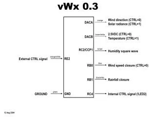
SHOT II Design – Thermal Control: • Foam insulation board provides passive thermal protection against the thermal environment at high altitude. • Heaters provide active means to providing heat to specific components. • Varying current through the thermistor provides microcontroller the temperature at the thermistor location. • At the specified “on” temperature (currently set to 15°C), microcontroller sends current to the LED and to the MOSFET, in turn signaling the heater to turn on. • Current will stop flowing to the MOSFET and the LED when temperature reaches the specified “off” value (20°C). Foam Insulation Board used for Box Structure Heater Circuit Diagram MOSFET
Expected Results: • Verification of nominal subsystem-subsystem interaction through log of command out and telemetry in to the Flight Compute Element • Thermistor Temperature • Heater ON/OFF • PMAD Board Voltage • Image acquisition at altitude • Verification of camera link to Flight Compute Element • PR Value! • Verification of on-board image processing routine on Flight Compute Element
Demonstration: Power on the Power Management & Distribution circuit Telemetry readout and heater switching on the Thermal Control subsystem