Download
1 / 31
380 likes | 852 Views
Prototyping the WAN. Designing and Supporting Computer Networks – Chapter 8. Objectives. Describe the methods to prototype remote connectivity support Prototype the WAN Connectivity Prototype the VPN connectivity for remote workers. 8.1.1 Describe Remote Connectivity Testing Methods.

E N D
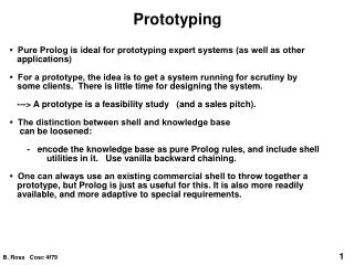
Prototyping the WAN Designing and Supporting Computer Networks – Chapter 8
Objectives • Describe the methods to prototype remote connectivity support • Prototype the WAN Connectivity • Prototype the VPN connectivity for remote workers
8.1.1 Describe Remote Connectivity Testing Methods • Testing Remote connectivity is more difficult than testing LAN design • Requires the use of transmission facilities not owned by the customer, such as Frame Relay, T1 connections or DSL • Three testing methods you can use are • Simulation software • Prototype testing using simulated links • Pilot testing in the actual environment
8.1.2 Advantages of Testing WAN Connectivity with Simulation Software • Lower overall cost—less expensive than building “test networks • Flexibility—Simulation software can support many different types of devices and connectivity options • Scalability—Permits testing of large networks in reduced amount of time • Control—Allows designer to control entire network operation at once • Network design can be tested before actually implemented
8.1.2 Disadvantages of Simulation Software • Limited functionality—Can easily become out of date and may not support all of the capabilities of the actual equipment • Unrealistic performance—difficult for the software programmers to anticipate and simulate all of the conditions that can occur in an actual network • Can do Show commands to test the network • SHOW INTERFACE command can show if you have an interface up and line protocol down • this could signify the encapsulation of the serial interface doesn’t match the encapsulation of the serial interface it is attached to • Both routers must have the same encapsulation!!! • Remember that usernames and passwords are bothcase sensitive when using chap • HDLC is the default encapsulation for serial interfaces of Cisco Routers
8.1.3 Simulating WAN Connectivity in a Lab Environment • Use Ethernet connection to simulate DSL or cable connection • Use a 10 mb connection • Connect routers with a crossover cable • Adjust routing protocol metrics of lower-speed link by using the bandwidth command • Use CSU/DSU, serial modems, or V.35 cables to simulate serial connectivity • Use DCE on one router • Set clockrate • Use DTE on the other router
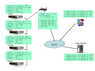
8.2.1 Identify WAN Goals and Requirements • Identify business goals and technical requirements from the case study and determine which of these goals and requirements can be tested in the prototype • Currently, the Remote sites use VPN connections of DSL Lines with no guarantee of bandwidth • Recommendation to upgrade to Frame Relay to connect TeamA and the FilmCompany • Existing VPNs will remain as a backup
Create a success criteria checklist to support business goals and technical requirements Frame Relay local loop configuration Mechanisms to activate the VPN backup link in the event of a Frame Relay failure Static routing configuration ACLs that filter traffic to and from the WAN sites SSH configuration to enable remote management 8.2.2 Creating the Test Plan
8.2.2 Creating the Test Plan In an Actual Frame Relay Implementation • Frame Relay local loop connects to a CSU/DSU at customer premise. • a serial connection is made to the customer premise equipment (CPE) router. • DCE function on the local loop is provided by TSP or the CSU/DSU. • Clocking for the serial connection between the CSU/DSU and the CPE router is provided by the CSU/DSU. • All of the connections at the router are DTE connections and use DTE cable. In a prototype test network • T1 or E1 connection to a Frame Relay switch does not exist. • It is simulated using a Cisco router acting as the Frame Relay switch • It is a router identified as FR1 • It connects to the other routers in the topology using a crossover connection • At the NetworkingCompany, this crossover function is created by connecting one V.35 DTE cable directly to a V.35 DCE cable. Because no CSU/DSU exists in the test topology, the FR1 router interfaces are configured with a clock rate to provide the DCE function.
8.2.2 Creating the Test Plan Determine the elements of the simulated WAN connection: • Simulate the Frame Relay connection using a Cisco router acting as a Frame Relay switch • Simulate a crossover function using V.35 cables • Provide the DCE function with a clock rate
8.2.2 Creating the Test Plan Output of a R2, which has been configured as a frame relay switch
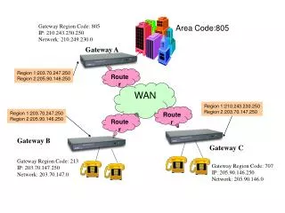
8.2.3 Validating the Choice of Devices and Topologies A Frame Relay Link is a virtual circuit that spans a series of connections and has three components • Local point-to-point circuit that connects the local CPE router to the TSP Frame Relay switch • TSP Packet-switched network • Remote point-to-point circuit that connects the remote site into the TSP network
8.2.3 Validating the Choice of Devices and Topologies • Local loop—connects the provider Frame Relay Switch to the CSU/DSU on the stadium premises • Local access rate—defines the rate at which data can travel into or out of the provider packet-switched network • Data-line Connection Identifier (DLCI) identifies each virtual circuit endpoint. • Is usually significant on the local loop. • Unique within a single Frame Relay switch • This DLCI number is placed in the address field of a frame that will travel from the source to the destination
8.2.3 Validating the Choice of Devices and Topologies • Guaranteed Data Rates—Frame Relay providers offer services with a guaranteed rate for the traffic transfer • CIR—committed information rate specifies the maximum average data rate the network delivers under normal conditions • DE—Discard eligible bit, this is a frame that the network flags as allowed to be deleted if necessary because of congestion • Zero CIR—means that every frame is a DE frame • This is an inexpensive Frame Relay option • Obviously not a good choice for mission-critical data • Local Management Interface—LMI is a signaling standard between the router (DTE) and the Frame Relay switch (DCE) • Uses keepalive (broadcasts sent by a network device to inform another network device that the VC is still active) messages to monitor the status of network connections • LMI standards can differ between networks but there are three types • ANSI, ITU-T, and Cisco
8.2.3 Validating the Choice of Devices and Topologies • Congestion Control is used to help manage network traffic flows • Forward-explicit congestion notification (FECN) • Informs the destination device about congestion on the network path • Backward-explicit congestion notification (BECN) • Informs the source device about congestion on the network path
8.2.4 Prototype the WAN Connectivity • Configure the router to act as the Frame Relay switch • Configure serial interfaces as DCE devices • Configure Layer 3 addresses and encapsulation type • Two choices are ietf and cisco • Default is cisco (it is proprietary)
8.2.4 Prototype the WAN Connectivity • Inverse ARP is used to build dynamic routes in a network. • Allows an access server to discover the network address of a device associated with a virtual circuit • Allows a router to know which DLCI is mapped to the IP address of a remote router • This is on by default • Multi-access—one physical interface can support multiple virtual circuits • Less expensive than dedicated point-to-point links • Point-to-point subinterface—single subinterface is used to establish one permanent virtual circuit • Multipoint subinterfaces—single subinterface is used to establish multiple PVC connections to multiple physical interfaces or subinterfaces on remote routers • Requires split horizon to be turned off (split horizon rule prevents routers from advertising a network through the interface from which the update came) • Requires IP addresses for each subinterface on each router to be a part of the same subnet
8.2.4 Prototype the WAN Connectivity Verify that the Frame Relay WAN operates as expected with the following commands • Display interface status with sho int serial • Verify LMI messages exchanged with sho frame-relay lmi • Display the status of PVCs with sho frame-relay pvc xxx • Display current entries learned through Invers ARP or statically configured maps and information about the connections with sho frame-relay map
8.2.5 Troubleshooting Frame Relay Operation Provide and test backup capabilities: • Set up Ethernet connections between routers • These are intended to simulate existing VPNs • Create floating static routes—a static route that has an administrative distance greater the administration distance of the corresponding dynamic routes • They will only be installed in the routing table if the other route is lost due to a link failure
8.2.5 Troubleshooting Frame Relay Operation • Troubleshoot Layer 1 using the show interface serial command • If interface is down and line protocol is down • If interface is up and line protocol is down, move on to next command • Troubleshoot Layer 2 using show frame-relay lmi command • Be sure LMI type is correct for the circuit • Type 1 indicates a keepalive LMI exchange • Type 0 is a full LMI status message • 0x0: DLCI not usable • 0x2: everything is operational • 0x4: if DLCIs are reversed on the router or if PVC was deleted in the Frame Relay cloud basically means the DLCI configured doesn’t match the DLCI on the interface • Check Layer 3 functionality • Verify no access control lists or IP routing table issues • Configure IP address-to-DLCI mapping by using the frame-relay map ip command
8.2.6 Identifying Risks and Weakenesses • Identify areas of risk and weakness in the design • is the performance of the VPN links functioning correctly when used as backups? • Are there quality of service issues when voice and video components are added?
8.3.1 Identify VPN goals and requirements Determine which business goals and technical requirements can be tested in the prototype: • VPN security by remotes workers (“trusted” users) • May be accessing the network from devices not fully secured or from locations in public areas such as airports and hotel lobbies • Ensure that remotes users can only access network resources that are appropriate for their job function • VPN server location—must be located at a point where incoming packets can be examined and filtered before being delivered to the internal network resources
8.3.2 Creating the Test Plan • Create a success criteria checklist to support business goals and technical requirements
8.3.2 Creating the Test Plan • Verify the use of Cisco EasyVPN to configure a VPN server and set up the client software by using Cisco SDM • Cisco EasyVPN Remote enables remote devices to receive security policies from a Cisco EasyVPN Server
8.3.3 Validate Choice of VPN Topology • Validate the choice of VPN technology, devices, and topologies • VPN Components • Tunneling to create the virtual network (created between the two endpoints) and is an extension of the local network across the WAN or public network through the encapsulation protocol • Encryption algorithm to enable privacy and security
8.3.3 Validate Choice of VPN Topology • Encryption Algorithms require a symmetric, shared secret key to perform encryption and decryption • Tunneling to create the virtual network (created between the two endpoints) and is an extension of the local network across the WAN or public network • Some cryptography to be used: • DH GROUP 1 - Uses 768-bit cryptography. • DH GROUP 2 - Cisco IOS, PIX Firewall, and Cisco Adaptive Security Appliances (ASA) devices only. Specifies to use 1024-bit cryptography. • DH GROUP 5 - Supported if the software system requirements are met. Specifies to use 1536-bit cryptography.
8.3.4 Prototype VPN Connectivity for Remote Workers • IPSec provides data confidentiality, data integrity and data authentication and operates at the OSI NETWORK layer • Relies on existing algorithms to implement these • Such as 3DES, AES and DES • Split tunnels • allows users to send only the traffic destined for the corporate network across the tunnel (this is encrypted) • Other traffic is sent out to the Internet via the local LAN of the VPN client and is not encrypted
8.3.5 Validate Placement of VPN Server • VPN Servers are placed at the WAN edge of a network
8.3.6 Identify Risks or Weaknesses • Identify risks or weaknesses in the VPN design • Work with the rest of the Networking Company staff to prepare the final design presentation for the network upgrade
Summary • Every Frame Relay link has three components: a local point-to-point circuit, the packet-switched network, and a remote point-to-point circuit. • Frame Relay is a nonbroadcast multi-access protocol. • One way to configure routers to use a backup link when a primary link fails is to create floating static routes. • VPNs have two important components: tunneling and encryption. • Encryption algorithms such as DES require a symmetric, shared secret key. • IPSec provides data confidentiality, integrity, and authentication at Layer 3.