Download
1 / 62
670 likes | 1.68k Views
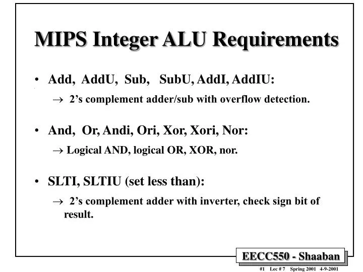
MIPS Integer ALU Requirements. Add, AddU, Sub, SubU, AddI, AddIU: 2’s complement adder/sub with overflow detection. And, Or, Andi, Ori, Xor, Xori, Nor: Logical AND, logical OR, XOR, nor. SLTI, SLTIU (set less than): 2’s complement adder with inverter, check sign bit of result.

E N D
MIPS Integer ALU Requirements • Add, AddU, Sub, SubU, AddI, AddIU: • 2’s complement adder/sub with overflow detection. • And, Or, Andi, Ori, Xor, Xori, Nor: • Logical AND, logical OR, XOR, nor. • SLTI, SLTIU (set less than): • 2’s complement adder with inverter, check sign bit of result.
MIPS Arithmetic Instructions Instruction Example Meaning Comments add add $1,$2,$3 $1 = $2 + $3 3 operands; exception possible subtract sub $1,$2,$3 $1 = $2 – $3 3 operands; exception possible add immediate addi $1,$2,100 $1 = $2 + 100 + constant; exception possible add unsigned addu $1,$2,$3 $1 = $2 + $3 3 operands; no exceptions subtract unsigned subu $1,$2,$3 $1 = $2 – $3 3 operands; no exceptions add imm. unsign. addiu $1,$2,100 $1 = $2 + 100 + constant; no exceptions multiply mult $2,$3 Hi, Lo = $2 x $3 64-bit signed product multiply unsigned multu$2,$3 Hi, Lo = $2 x $3 64-bit unsigned product divide div $2,$3 Lo = $2 ÷ $3, Lo = quotient, Hi = remainder Hi = $2 mod $3 divide unsigned divu $2,$3 Lo = $2 ÷ $3, Unsigned quotient & remainder Hi = $2 mod $3 Move from Hi mfhi $1 $1 = Hi Used to get copy of Hi Move from Lo mflo $1 $1 = Lo Used to get copy of Lo
31 25 20 15 5 0 R-type: op Rs Rt Rd funct I-Type: op Rs Rt Immed 16 Type op funct ADDI 10 xx ADDIU 11 xx SLTI 12 xx SLTIU 13 xx ANDI 14 xx ORI 15 xx XORI 16 xx LUI 17 xx Type op funct ADD 00 40 ADDU 00 41 SUB 00 42 SUBU 00 43 AND 00 44 OR 00 45 XOR 00 46 NOR 00 47 Type op funct 00 50 00 51 SLT 00 52 SLTU 00 53 MIPS Arithmetic Instruction Format
c zero MIPS Integer ALU Requirements (1) Functional Specification: inputs: 2 x 32-bit operands A, B, 4-bit mode outputs: 32-bit result S, 1-bit carry, 1 bit overflow, 1 bit zero operations: add, addu, sub, subu, and, or, xor, nor, slt, sltU (2) Block Diagram: 00 add 01 addU 02 sub 03 subU 04 and 05 or 06 xor 07 nor 12 slt 13 sltU 10 operations thus 4 control bits 32 32 A B 4 ALU m ovf S 32
CarryIn A 1-bit Full Adder Sum B CarryOut Building Block: 1-bit Full Adder
Operation invertB CarryIn and A or Result Mux add 1-bit Full Adder CarryOut B Building Block: 1-bit ALU Performs: AND, OR, addition on A, B or A, B inverted
CarryIn0 A0 1-bit ALU Result0 B0 CarryOut0 CarryIn1 A1 1-bit ALU Result1 B1 CarryOut1 CarryIn2 A2 1-bit ALU Result2 B2 : : CarryIn3 CarryIn31 CarryOut30 A31 1-bit ALU Result31 B31 CarryOut31 C 32-Bit ALU Using 32 1-Bit ALUs 32-bit rippled-carry adder (operation/invertB lines not shown) Addition/Subtraction Performance: Total delay = 32 x (1-Bit ALU Delay) = 32 x 2 x gate delay = 64 x gate delay
CarryIn0 A0 1-bit ALU Result0 B0 CarryOut0 CarryIn1 Zero A1 1-bit ALU Result1 B1 CarryOut1 CarryIn2 A2 1-bit ALU Result2 : : : : B2 CarryIn3 : : CarryOut30 CarryIn31 Overflow A31 1-bit ALU Result31 B31 CarryOut31 C Adding Overflow/Zero Detection Logic • For a N-bit ALU: Overflow = CarryIn[N - 1] XOR CarryOut[N - 1]
Adding Support For SLT • In SLT if A < B , the least significant result bit is set to 1. • Perform A - B, A < B if sign bit is 1 • Use sign bit as Result0 setting all other result bits to zero. Modified 1-Bit ALU Operation invertB CarryIn and A Control values: 000 = and001 = or010 = add110 = subtract111 = slt or Result Mux add 1-bit Full Adder Operation MUX select invertB B slt Less position 0: connected to sign bit, Result31 positions 1-31: set to 0 CarryOut
CarryIn0 A0 1-bit ALU B0 Result0 Less CarryOut0 CarryIn1 A1 1-bit ALU Result1 B1 Zero Less = 0 Less = 0 Less = 0 CarryOut1 CarryIn2 A2 1-bit ALU Result2 B2 : : : : CarryIn3 : : CarryOut30 CarryIn31 A31 Overflow 1-bit ALU B31 Result31 CarryOut31 C MIPS ALU With SLT Support Added
Improving ALU Performance: Carry Look Ahead (CLA) Cin A B C-out 0 0 0 “kill” 0 1 C-in “propagate” 1 0 C-in “propagate” 1 1 1 “generate” A0 S G B1 P C1 =G0 + C0 P0 A S G = A and B P = A xor B G B P C2 = G1 + G0 P1 + C0 P0 P1 A S G B P C3 = G2 + G1 P2 + G0 P1 P2 + C0 P0 P1 P2 A S G G B P P C4 = . . .
C0 C L A G0 P0 C1 =G0 + C0 P0 4-bit Adder C2 = G1 + G0 P1 + C0 P0 P1 4-bit Adder C3 = G2 + G1 P2 + G0 P1 P2 + C0 P0 P1 P2 G 4-bit Adder P C4 = . . . Cascaded Carry Look-ahead 16-Bit Example Delay = 2 + 2 + 1 = 5 gate delays { Assuming all gates have equal delay
Additional MIPS ALU requirements • Mult, MultU, Div, DivU: => Need 32-bit multiply and divide, signed and unsigned. • Sll, Srl, Sra: => Need left shift, right shift, right shift arithmetic by 0 to 31 bits. • Nor: => logical NOR to be added.
Unsigned Multiplication Example • Paper and pencil example (unsigned): Multiplicand 1000Multiplier 1001 1000 0000 0000 1000 Product 01001000 • m bits x n bits = m + n bit product, m = 32, n = 32, 64 bit product. • The binary number system simplifies multiplication: 0 => place 0 ( 0 x multiplicand). 1 => place a copy ( 1 x multiplicand). • We will examine 4 versions of multiplication hardware & algorithm: • Successive refinement of design.
0 0 0 0 A3 A2 A1 A0 B0 A3 A2 A1 A0 B1 A3 A2 A1 A0 B2 A3 A2 A1 A0 B3 P7 P6 P5 P4 P3 P2 P1 P0 An Unsigned Combinational Multiplier 4-bit adder • Stage i accumulates A * 2 i if Bi == 1 • How much hardware for a 32-bit multiplier? Critical path? 4 x 4 multiplier
0 0 0 0 0 0 0 A3 A2 A1 A0 B0 A3 A2 A1 A0 B1 A3 A2 A1 A0 B2 A3 A2 A1 A0 B3 P7 P6 P5 P4 P3 P2 P1 P0 Operation of Combinational Multiplier • At each stage shift A left ( x 2). • Use next bit of B to determine whether to add in shifted multiplicand. • Accumulate 2n bit partial product at each stage.
Shift Left Multiplicand 64 bits Multiplier Shift Right 64-bit ALU 32 bits Write Product Control 64 bits Multiplier = datapath + control Unsigned Shift-Add Multiplier (version 1) • 64-bit Multiplicand register. • 64-bit ALU. • 64-bit Product register. • 32-bit multiplier register.
Start Multiplier0 = 1 Multiplier0 = 0 1. Test Multiplier0 1a. Add multiplicand to product & place the result in Product register 2. Shift the Multiplicand register left 1 bit. 3. Shift the Multiplier register right 1 bit. 32nd repetition? No: < 32 repetitions Yes: 32 repetitions Done Multiply Algorithm Version 1 Product Multiplier Multiplicand 0000 0000 0011 0000 0010 0000 0010 0001 0000 0100 0000 0110 0000 0000 1000 0000 0110
Multiplicand 32 bits Multiplier Shift Right 32-bit ALU 32 bits Shift Right Product Control Write 64 bits MULTIPLY HARDWARE Version 2 • Instead of shifting multiplicand to left, shift product to right: • 32-bit Multiplicand register. • 32 -bit ALU. • 64-bit Product register. • 32-bit Multiplier register.
Start Multiplier0 = 1 Multiplier0 = 0 1. Test Multiplier0 1a. Add multiplicand to the left half ofproduct & place the result in the left half ofProduct register 2. Shift the Product register right 1 bit. 3. Shift the Multiplier register right 1 bit. 32nd repetition? No: < 32 repetitions Yes: 32 repetitions Done Multiply Algorithm Version 2 Product Multiplier Multiplicand 0000 0000 0011 0010 0010 0000 0001 00000001 0010 0011 00 0001 0010 0001 1000 0000 0010 0000 1100 0000 0010 0000 0110 0000 0010
0 0 0 0 A3 A2 A1 A0 B0 A3 A2 A1 A0 B1 A3 A2 A1 A0 B2 A3 A2 A1 A0 B3 P7 P6 P5 P4 P3 P2 P1 P0 Multiplication Version 2 Operation • Multiplicand stays still and product moves right.
Multiplicand 32 bits 32-bit ALU Shift Right Product (Multiplier) Control Write 64 bits MULTIPLY HARDWARE Version 3 • Combine Multiplier register and Product register: • 32-bit Multiplicand register. • 32 -bit ALU. • 64-bit Product register, (0-bit Multiplier register).
1. Test Product0 1a. Add multiplicand to the left half of product & place the result in the left half of Product register Start Multiply Algorithm Version 3 Product0 = 1 Product0 = 0 2. Shift the Product register right 1 bit. 32nd repetition? No: < 32 repetitions Yes: 32 repetitions Done
Observations on Multiply Version 3 • 2 steps per bit because Multiplier & Product are combined. • MIPS registers Hi and Lo are left and right halves of Product. • Provides the MIPS instruction MultU. • What about signed multiplication? • The easiest solution is to make both positive & remember whether to complement product when done (leave out the sign bit, run for 31 steps). • Apply definition of 2’s complement: • Need to sign-extend partial products and subtract at the end. • Booth’s Algorithm is an elegant way to multiply signed numbers using the same hardware as before and save cycles: • Can handle multiple bits at a time.
Motivation for Booth’s Algorithm • Example 2 x 6 = 0010 x 0110: 0010 x 0110 + 0000 shift (0 in multiplier) + 0010 add (1 in multiplier) + 0100 add (1 in multiplier) + 0000 shift (0 in multiplier) 00001100 • An ALU with add or subtract gets the same result in more than one way: 6 = – 2 + 8 0110 = – 00010 + 01000 = 11110 + 01000 • For example: 0010 x 0110 0000 shift (0 in multiplier) – 0010 sub (first 1 in multpl.) . 0000 shift (mid string of 1s) . + 0010 add (prior step had last 1) 00001100
Booth’s Algorithm Current Bit Bit to the Right Explanation Example Op 1 0 Begins run of 1s 0001111000 sub 1 1 Middle of run of 1s 0001111000 none 0 1 End of run of 1s 0001111000 add 0 0 Middle of run of 0s 0001111000 none • Originally designed for Speed (when shift was faster than add). • Replace a string of 1s in multiplier with an initial subtract when we first see a one and then later add for the bit after the last one.
Booth Example (2 x 7) 1a. P = P - m 1110 + 1110 1110 0111 0 shift P (sign ext) 1b. 0010 1111 00111 11 -> nop, shift 2. 0010 1111 10011 11 -> nop, shift 3. 0010 1111 11001 01 -> add 4a. 0010 + 0010 0001 11001 shift 4b. 0010 0000 1110 0 done Operation Multiplicand Product next? 0. initial value 0010 0000 0111 0 10 -> sub
Booth Example (2 x -3) Operation Multiplicand Product next? 0. initial value 0010 0000 1101 0 10 -> sub 1a. P = P - m 1110 + 1110 1110 1101 0 shift P (sign ext) 1b. 0010 1111 01101 01 -> add + 0010 2a. 0001 01101 shift P 2b. 0010 0000 10110 10 -> sub + 1110 3a. 0010 1110 10110 shift 3b. 0010 1111 0101 1 11 -> nop 4a 1111 0101 1 shift 4b. 0010 1111 10101 done
MIPS Logical Instructions Instruction Example Meaning Comment and and $1,$2,$3 $1 = $2 & $3 3 reg. operands; Logical AND or or $1,$2,$3 $1 = $2 | $3 3 reg. operands; Logical OR xor xor $1,$2,$3 $1 = $2 $3 3 reg. operands; Logical XOR nor nor $1,$2,$3 $1 = ~($2 |$3) 3 reg. operands; Logical NOR and immediate andi $1,$2,10 $1 = $2 & 10 Logical AND reg, constant or immediate ori $1,$2,10 $1 = $2 | 10 Logical OR reg, constant xor immediate xori $1, $2,10 $1 = ~$2 &~10 Logical XOR reg, constant shift left logical sll $1,$2,10 $1 = $2 << 10 Shift left by constant shift right logical rl $1,$2,10 $1 = $2 >> 10 Shift right by constant shift right arithm. sra $1,$2,10 $1 = $2 >> 10 Shift right (sign extend) shift left logical sllv $1,$2,$3 $1 = $2 << $3 Shift left by variable shift right logical srlv $1,$2, $3 $1 = $2 >> $3 Shift right by variable shift right arithm. srav $1,$2, $3 $1 = $2 >> $3 Shift right arith. by variable
1 0 S2 S1 S0 A7 A6 A5 A4 A3 A2 A1 A0 1 1 1 1 1 1 1 1 0 0 0 0 0 0 0 0 1 1 1 1 1 1 1 1 0 0 0 0 0 0 0 0 1 1 1 1 1 1 1 1 0 0 0 0 0 0 0 0 R7 R6 R5 R4 R3 R2 R1 R0 Combinational Shifter from MUXes B A Basic Building Block • What comes in the MSBs? • How many levels for 32-bit shifter? sel D 8-bit right shifter
S 0 (0,1) S 1 (0, 2) S 2 (0, 4) S 3 (0, 8) General Shift Right Scheme Using 16-Bit Example If added Right-to-left connections could support Rotate (not in MIPS but found in ISAs)
SR3 SR2 SR1 SR0 D3 D2 A6 D1 A5 D0 A4 A3 A2 A1 A0 Barrel Shifter Technology-dependent solution: a transistor per switch
Division 1001 Quotient Divisor 1000 1001010 Dividend–1000 10 101 1010 –1000 10 Remainder (or Modulo result) • See how big a number can be subtracted, creating quotient bit on each step: Binary => 1 * divisor or 0 * divisor Dividend = Quotient x Divisor + Remainder => | Dividend | = | Quotient | + | Divisor | • 3 versions of divide, successive refinement
Shift Right Divisor 64 bits Quotient Shift Left 64-bit ALU 32 bits Write Remainder Control 64 bits DIVIDE HARDWARE Version 1 • 64-bit Divisor register. • 64-bit ALU. • 64-bit Remainder register. • 32-bit Quotient register.
Start: Place Dividend in Remainder 1. Subtract the Divisor register from the Remainder register, and place the result in the Remainder register. Remainder < 0 Test Remainder Remainder >= 0 2b. Restore the original value by adding the Divisor register to the Remainder register, & place the sum in the Remainder register. Also shift the Quotient register to the left, setting the new least significant bit to 0. 2a. Shift the Quotient register to the left setting the new rightmost bit to 1. 3. Shift the Divisor register right1 bit. n+1 repetition? No: < n+1 repetitions Yes: n+1 repetitions (n = 4 here) Done Divide Algorithm Version 1 Takes n+1 steps for n-bit Quotient & Rem.
Observations on Divide Version 1 • 1/2 bits in divisor are always 0. => 1/2 of 64-bit adder is wasted. => 1/2 of divisor is wasted. • Instead of shifting divisor to right, shift remainder to left? • 1st step cannot produce a 1 in quotient bit (otherwise too big). => Switch order to shift first and then subtract, can save 1 iteration.
Divisor 32 bits Quotient Shift Left 32-bit ALU 32 bits Shift Left Remainder Control Write 64 bits DIVIDE HARDWARE Version 2 • 32-bit Divisor register. • 32-bit ALU. • 64-bit Remainder register. • 32-bit Quotient register.
Start: Place Dividend in Remainder 1. Shift the Remainder register left 1 bit. 2. Subtract the Divisor register from the left half of the Remainder register, & place the result in the left half of the Remainder register. Remainder >= 0 Test Remainder Remainder < 0 3b. Restore the original value by adding the Divisor register to the left half of the Remainderregister, &place the sum in the left half of the Remainder register. Also shift the Quotient register to the left, setting the new least significant bit to 0. 3a. Shift the Quotient register to the left setting the new rightmost bit to 1. nth repetition? No: < n repetitions Yes: n repetitions (n = 4 here) Done Divide Algorithm Version 2
Observations on Divide Version 2 • Eliminate Quotient register by combining with Remainder as shifted left: • Start by shifting the Remainder left as before. • Thereafter loop contains only two steps because the shifting of the Remainder register shifts both the remainder in the left half and the quotient in the right half. • The consequence of combining the two registers together and the new order of the operations in the loop is that the remainder will shifted left one time too many. • Thus the final correction step must shift back only the remainder in the left half of the register.
Divisor 32 bits 32-bit ALU “HI” “LO” Shift Left (Quotient) Remainder Control Write 64 bits DIVIDE HARDWARE Version 3 • 32-bit Divisor register. • 32 -bit ALU. • 64-bit Remainder register (0-bit Quotient register).
Start: Place Dividend in Remainder 1. Shift the Remainder register left 1 bit. 2. Subtract the Divisor register from the left half of the Remainder register, & place the result in the left half of the Remainder register. Test Remainder Remainder < 0 Remainder >= 0 3b. Restore the original value by adding the Divisor register to the left half of the Remainderregister, &place the sum in the left half of the Remainder register. Also shift the Remainder register to the left, setting the new least significant bit to 0. 3a. Shift the Remainder register to the left setting the new rightmost bit to 1. nth repetition? No: < n repetitions Yes: n repetitions (n = 4 here) Done. Shift left half of Remainder right 1 bit. Divide Algorithm Version 3
Observations on Divide Version 3 • Same Hardware as Multiply: Just requires an ALU to add or subtract, and 64-bit register to shift left or shift right. • Hi and Lo registers in MIPS combine to act as 64-bit register for multiply and divide. • Signed Divides: Simplest is to remember signs, make positive, and complement quotient and remainder if necessary. • Note: • Dividend and Remainder must have same sign. • Quotient negated if Divisor sign & Dividend sign disagree. • e.g., –7 ÷ 2 = –3, remainder = –1 • Possible for quotient to be too large: If dividing a 64-bit integer by 1, quotient is 64 bits (“called saturation”).
Exponent Decimal point 25 -24 5.04 x 10 - 1.673 x 10 Sign, Magnitude Radix (base) Mantissa Sign, Magnitude Scientific Notation
1 8 23 E sign M S mantissa: sign + magnitude, normalized binary significand with a hidden integer bit: 1.M exponent: excess 127 binary integer added 0 < E <255 Actual exponent is: e = E - 127 -126 127 -23 ) 2 (1.0) (2 - 2 to 2 - 38 38 to 3.40 x 10 1.8 x 10 Representation of Floating Point Numbers inSingle PrecisionIEEE 754 Standard Value = N = (-1)S X 2 E-127 X (1.M) Example: 0 = 0 00000000 0 . . . 0 -1.5 = 1 01111111 10 . . . 0 Magnitude of numbers that can be represented is in the range: Which is approximately:
1 11 52 E sign M S Mantissa: sign + magnitude, normalized binary significand with a hidden integer bit: 1.M exponent: excess 1023 binary integer added 0 < E < 2047 Actual exponent is: e = E - 1023 -1022 1023 - 52 ) 2 (1.0) (2 - 2 to 2 - 308 308 to 1.8 x 10 2.23 x 10 Representation of Floating Point Numbers inDouble PrecisionIEEE 754 Standard Value = N = (-1)S X 2 E-1023 X (1.M) Example: 0 = 0 00000000000 0 . . . 0 -1.5 = 1 01111111111 10 . . . 0 Magnitude of numbers that can be represented is in the range: Which is approximately:
IEEE 754 Special Number Representation Single Precision Double Precision Number Represented Exponent Significand Exponent Significand 0 0 0 0 0 0 nonzero 0 nonzero Denormalized number1 1 to 254 anything 1 to 2046 anything Floating Point Number 255 0 2047 0 Infinity2 255 nonzero 2047 nonzero NaN (Not A Number)3 1 May be returned as a result of underflow in multiplication 2 Positive divided by zero yields “infinity” 3 Zero divide by zero yields NaN “not a number”
Floating Point Conversion Example • The decimal number .7510 is to be represented in the IEEE 754 32-bit single precision format: -2345.12510 = 0.112 (converted to a binary number) = 1.1 x 2-1 (normalized a binary number) • The mantissa is positive so the sign S is given by: S = 0 • The biased exponent E is given by E = e + 127 E = -1 + 127 = 12610 = 011111102 • Fractional part of mantissa M: M = .10000000000000000000000 (in 23 bits) The IEEE 754 single precision representation is given by: 0 01111110 10000000000000000000000 S E M 1 bit 8 bits 23 bits Hidden
Hidden Floating Point Conversion Example • The decimal number -2345.12510 is to be represented in the IEEE 754 32-bit single precision format: -2345.12510 = -100100101001.0012 (converted to binary) = -1.00100101001001 x 211 (normalized binary) • The mantissa is negative so the sign S is given by: S = 1 • The biased exponent E is given by E = e + 127 E = 11 + 127 = 13810 = 100010102 • Fractional part of mantissa M: M = .00100101001001000000000 (in 23 bits) The IEEE 754 single precision representation is given by: 1 10001010 00100101001001000000000 S E M 1 bit 8 bits 23 bits
Basic Floating Point Addition Algorithm • Assuming that the operands are already in the IEEE 754 format, performing floating point addition: Result = X + Y = (Xm x 2Xe) + (Ym x 2Ye) • involves the following steps: • (1) Align binary point: • Initial result exponent: the larger of Xe, Ye • Compute exponent difference: Ye - Xe • If Ye > Xe Right shift Xm that many positions to form Xm 2 Xe-Ye • If Xe > Ye Right shift Ym that many positions to form Ym 2 Ye-Xe • (2) Compute sum of aligned mantissas: • i.e Xm2 Xe-Ye + Ym or Xm + Xm2 Ye-Xe • (3) If normalization of result is needed, then a normalization step follows: • Left shift result, decrement result exponent (e.g., if result is 0.001xx…) or • Right shift result, increment result exponent (e.g., if result is 10.1xx…) • Continue until MSB of data is 1 (NOTE: Hidden bit in IEEE Standard). • (4)Doubly biased exponent must be corrected: extra subtraction step of the bias • amount. • (5) Check result exponent: • If larger than maximum exponent allowed return exponent overflow • If smaller than minimum exponent allowed return exponent underflow • (6) Round the significand and re-normalize if needed. If result mantissa is 0, may • need to set the exponent to zero by a special step to return a proper zero.
Compare the exponents of the two numbers shift the smaller number to the right until its exponent matches the larger exponent Add the significands (mantissas) Normalize the sum, either shifting right and incrementing the exponent or shifting left and decrementing the exponent Generate exception or return error Round the significand to the appropriate number of bits If mantissa = 0, set exponent to 0 Done Start Floating Point Addition Flowchart (1) (2) (3) (4) Yes Overflow or Underflow ? No No Still normalized? yes (5)