Download

1 / 49
490 likes | 701 Views
ALU. S.Rawat. ALU. ALU an Engine for any Computational Silicon. We have different units ALU/FPUs for Integers/Floats respectively. Mainly Decided based on the fact that FP must be pipelined to be in harmony with other blocks in the design.

E N D
ALU S.Rawat
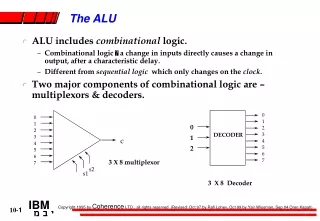
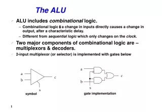
ALU • ALU an Engine for any Computational Silicon. • We have different units ALU/FPUs for Integers/Floats respectively. • Mainly Decided based on the fact that FP must be pipelined to be in harmony with other blocks in the design. • While ALU mainly Single Cycle Operation if we are in given Timing Bucket. • So the Fast-Parallel Systolic Array implementation of Computational blocks is one of the main concern.
Further Classification Based on Application • Now What all kind of operation an ALU must Support. • Lets take an example of IIR/FIR Filters i.e. DSP processor. • Where Frequently performed operation is for an example consider a second order FIR. Y[n] = a0*x[n] + a1*x[n-1] + a2*x[n-3]. • Either Implement MAC Units or perform using separate multiplication and addition
Further Classification Based on Application • So the idea is that depending upon the Application one might have an ALU where normal Arithmetic and Logical operations are frequent or DSP shifts and MAC more Frequent. • Why this is important is because it has to be decided initially before starting any computational device according to given Timing and Power Bucket.
Few More Deciding Points • An ALU is supposed to fit-in either Finite Field Arithmetic or with the allowed range infinite field arithmetic (i.e. Integer ALU of some generic processor). • Present Superscalar processors have separate FPU (Floating Point Unit) and Integer ALU. • For Communication Dedicated processor where Finite Field Arithmetic is needed to encode and decode, Finite Field ALUs are designed, where the Number Line becomes Cyclic and interpretation of + * / is changed according to periodicity.
Fundamentally its very Simple • But Complexity come from the interfaces where, it fits in the Execution unit, and forms interfaces with Superscalar-Fetch and Store-Unit. • Complexity in terms of maintaining the latency, across the operation.
Lets Take an Example of Int. ALU • Divide and Conquer (e.g., ALU) • Formulate a solution in terms of simpler components. • Design each of the components (subproblems) • Generate and Test (e.g., ALU) • Given a collection of building blocks, look for ways of putting them together that meets requirement • Successive Refinement (e.g., multiplier, divider) • Solve "most" of the problem (i.e., ignore some constraints or special cases), examine and correct shortcomings. • Formulate High-Level Alternatives (e.g., shifter) • Articulate many strategies to "keep in mind" while pursuing any one approach. • Work on the Things you Know How to Do • The unknown will become “obvious” as you make progress.
Review: Summary of the Design Process Hierarchical Design to manage complexity Top Down vs. Bottom Up vs. Successive Refinement Importance of Design Representations: Block Diagrams Decomposition into Bit Slices Truth Tables, K-Maps Circuit Diagrams Other Descriptions: state diagrams, timing diagrams, reg xfer, . . . Optimization Criteria: Gate Count [Package Count] top down bottom up Area Logic Levels Fan-in/Fan-out Delay Power Pin Out Cost Design time
Representation Languages Hardware Representation Languages: Block Diagrams: FUs, Registers, & Dataflows Register Transfer Diagrams: Choice of busses to connect FUs, Regs Flowcharts State Diagrams Fifth Representation "Language": Hardware Description Languages E.G., ISP' Verilog Descriptions in these languages can be used as input to simulation systems synthesis systems Two different ways to describe sequencing & microoperations hw modules described like programs with i/o ports, internal state, & parallel execution of assignment statements "software breadboard" generate hw from high level description "To Design is to Represent"
Simulation Before Construction "Physical Breadboarding" discrete components/lower scale integration preceeds actual construction of prototype verify initial design concept No longer possible as designs reach higher levels of integration! Simulation Before Construction high level constructs implies faster to construct play "what if" more easily limited performance accuracy, however
Levels of Description Architectural Simulation Functional/Behavioral Register Transfer Logic Circuit models programmer's view at a high level; written in your favorite programming language more detailed model, like the block diagram view commitment to datapath FUs, registers, busses; register xfer operations are clock phase accurate model is in terms of logic gates; higher level MSI functions described in terms of these electrical behavior; accurate waveforms Less Abstract More Accurate Slower Simulation Schematic capture + logic simulation package like Powerview Special languages + simulation systems for describing the inherent parallel activity in hardware
Verilog • Goals: • Support design, documentation, and simulation of hardware • Digital system level to gate level • “Technology Insertion” • Concepts: • Design entity • Time-based execution model. Interface == External Characteristics Design Entity == Hardware Component Architecture (Body ) == Internal Behavior or Structure
Interface • Externally Visible Characteristics • Ports: channels of communication • (inputs, outputs, clocks, control) • Generic Parameters: define class of components • (timing characteristics, size, fan-out) --- determined where instantiated or by default • Internally Visible Characteristics • Declarations: • Assertions: constraints on all alternative bodies • (i.e., implementations) Interface view to other modules Architecture details of implementation
MIPS arithmetic instructions • Instruction Example Meaning Comments • add add $1,$2,$3 $1 = $2 + $3 3 operands; exception possible • subtract sub $1,$2,$3 $1 = $2 – $3 3 operands; exception possible • add immediate addi $1,$2,100 $1 = $2 + 100 + constant; exception possible • add unsigned addu $1,$2,$3 $1 = $2 + $3 3 operands; no exceptions • subtract unsigned subu $1,$2,$3 $1 = $2 – $3 3 operands; no exceptions • add imm. unsign. addiu $1,$2,100 $1 = $2 + 100 + constant; no exceptions • multiply mult $2,$3 Hi, Lo = $2 x $3 64-bit signed product • multiply unsigned multu$2,$3 Hi, Lo = $2 x $3 64-bit unsigned product • divide div $2,$3 Lo = $2 ÷ $3, Lo = quotient, Hi = remainder • Hi = $2 mod $3 • divide unsigned divu $2,$3 Lo = $2 ÷ $3, Unsigned quotient & remainder Hi = $2 mod $3 • Move from Hi mfhi $1 $1 = Hi Used to get copy of Hi • Move from Lo mflo $1 $1 = Lo Used to get copy of Lo
MULTIPLY (unsigned) • Paper and pencil example (unsigned): Multiplicand 1000 Multiplier 1001 1000 0000 0000 1000 Product 01001000 • m bits x n bits = m+n bit product • Binary makes it easy: • 0 => place 0 ( 0 x multiplicand) • 1 => place a copy ( 1 x multiplicand) • 4 versions of multiply hardware & algorithm: • successive refinement
Unsigned Combinational Multiplier 0 0 0 0 A3 A2 A1 A0 B0 A3 A2 A1 A0 B1 A3 A2 A1 A0 B2 A3 A2 A1 A0 B3 P7 P6 P5 P4 P3 P2 P1 P0 • Stage i accumulates A * 2 i if Bi == 1 • Q: How much hardware for 32 bit multiplier? Critical path?
How does it work? A3 A2 A1 A0 A3 A2 A1 A0 A3 A2 A1 A0 A3 A2 A1 A0 0 0 0 0 0 0 0 B0 B1 B2 B3 P7 P6 P5 P4 P3 P2 P1 P0 • at each stage shift A left ( x 2) • use next bit of B to determine whether to add in shifted multiplicand • accumulate 2n bit partial product at each stage
Unisigned shift-add multiplier (version 1) • 64-bit Multiplicand reg, 64-bit ALU, 64-bit Product reg, 32-bit multiplier reg Shift Left Multiplicand 64 bits Multiplier Shift Right 64-bit ALU 32 bits Write Product Control 64 bits Multiplier = datapath + control
Multiply Algorithm Version 1 1. Test Multiplier0 Start Multiplier0 = 1 Multiplier0 = 0 1a. Add multiplicand to product & place the result in Product register • Product Multiplier Multiplicand • 0000 0000 0011 0000 0010 • 0000 0010 0001 0000 0100 • 0000 0110 0000 0000 1000 • 0000 0110 2. Shift the Multiplicand register left 1 bit. 3. Shift the Multiplier register right 1 bit. 32nd repetition? No: < 32 repetitions Yes: 32 repetitions Done
Observations on Multiply Version 1 • 1 clock per cycle => 100 clocks per multiply • Ratio of multiply to add 5:1 to 100:1 • 1/2 bits in multiplicand always 0=> 64-bit adder is wasted • 0’s inserted in left of multiplicand as shifted=> least significant bits of product never changed once formed • Instead of shifting multiplicand to left, shift product to right?
MULTIPLY HARDWARE Version 2 • 32-bit Multiplicand reg, 32 -bit ALU, 64-bit Product reg, 32-bit Multiplier reg Multiplicand 32 bits Multiplier Shift Right 32-bit ALU 32 bits Shift Right Product Control Write 64 bits
Multiply Algorithm Version 2 1. Test Multiplier0 1a. Add multiplicand to the left half ofproduct & place the result in the left half ofProduct register Start Multiplier Multiplicand Product0011 0010 0000 0000 Multiplier0 = 1 Multiplier0 = 0 • Product Multiplier Multiplicand 0000 0000 0011 0010 2. Shift the Product register right 1 bit. 3. Shift the Multiplier register right 1 bit. 32nd repetition? No: < 32 repetitions Yes: 32 repetitions Done
What’s going on? A3 A2 A1 A0 A3 A2 A1 A0 A3 A2 A1 A0 A3 A2 A1 A0 0 0 0 0 B0 B1 B2 B3 P7 P6 P5 P4 P3 P2 P1 P0 • Multiplicand stay’s still and product moves right
Observations on Multiply Version 2 • Product register wastes space that exactly matches size of multiplier=> combine Multiplier register and Product register
MULTIPLY HARDWARE Version 3 • 32-bit Multiplicand reg, 32 -bit ALU, 64-bit Product reg, (0-bit Multiplier reg) Multiplicand 32 bits 32-bit ALU Shift Right Product (Multiplier) Control Write 64 bits
1. Test Product0 1a. Add multiplicand to the left half of product & place the result in the left half of Product register Multiply Algorithm Version 3 Start Product0 = 1 Product0 = 0 Multiplicand Product0010 0000 0011 2. Shift the Product register right 1 bit. 32nd repetition? No: < 32 repetitions Yes: 32 repetitions Done
Observations on Multiply Version 3 • 2 steps per bit because Multiplier & Product combined • MIPS registers Hi and Lo are left and right half of Product • Gives us MIPS instruction MultU • How can you make it faster? • What about signed multiplication? • easiest solution is to make both positive & remember whether tocomplement product when done (leave out the sign bit, run for 31 steps) • apply definition of 2’s complement • need to sign-extend partial products and subtract at the end • Booth’s Algorithm is elegant way to multiply signed numbers using same hardware as before and save cycles • can handle multiple bits at a time
Motivation for Booth’s Algorithm • Example 2 x 6 = 0010 x 0110: 0010 x 0110 + 0000 shift (0 in multiplier) + 0010 add (1 in multiplier) + 0010 add (1 in multiplier) + 0000 shift (0 in multiplier) 00001100 • ALU with add or subtract gets same result in more than one way: 6 = – 2 + 8 0110 = – 00010 + 01000 = 11110 + 01000 • For example • 0010 x 0110 0000 shift (0 in multiplier) –0010 sub (first 1 in multpl.).0000 shift (mid string of 1s) . + 0010 add (prior step had last 1) 00001100
–1 + 10000 01111 Booth’s Algorithm Current Bit Bit to the Right Explanation Example Op 1 0 Begins run of 1s 0001111000 sub 1 1 Middle of run of 1s 0001111000 none 0 1 End of run of 1s 0001111000 add 0 0 Middle of run of 0s 0001111000 none Originally for Speed (when shift was faster than add) • Replace a string of 1s in multiplier with an initial subtract when we first see a one and then later add for the bit after the last one
Booths Example (2 x 7) Operation Multiplicand Product next? 0. initial value 0010 0000 0111 0 10 -> sub 1a. P = P - m 1110 + 1110 1110 0111 0 shift P (sign ext) 1b. 0010 1111 00111 11 -> nop, shift 2. 0010 1111 10011 11 -> nop, shift 3. 0010 1111 11001 01 -> add 4a. 0010 + 0010 0001 11001 shift 4b. 0010 0000 1110 0 done
Booths Example (2 x -3) Operation Multiplicand Product next? 0. initial value 0010 0000 1101 0 10 -> sub 1a. P = P - m 1110 +1110 1110 1101 0 shift P (sign ext) 1b. 0010 1111 01101 01 -> add +0010 2a. 0001 01101shift P 2b. 0010 0000 10110 10 -> sub +1110 3a. 0010 1110 10110 shift 3b. 0010 1111 0101111 -> nop 4a 1111 01011 shift 4b. 0010 1111 10101 done
MIPS logical instructions • Instruction Example Meaning Comment • and and $1,$2,$3 $1 = $2 & $3 3 reg. operands; Logical AND • or or $1,$2,$3 $1 = $2 | $3 3 reg. operands; Logical OR • xor xor $1,$2,$3 $1 = $2 Å $3 3 reg. operands; Logical XOR • nor nor $1,$2,$3 $1 = ~($2 |$3) 3 reg. operands; Logical NOR • and immediate andi $1,$2,10 $1 = $2 & 10 Logical AND reg, constant • or immediate ori $1,$2,10 $1 = $2 | 10 Logical OR reg, constant • xor immediate xori $1, $2,10 $1 = ~$2 &~10 Logical XOR reg, constant • shift left logical sll $1,$2,10 $1 = $2 << 10 Shift left by constant • shift right logical srl $1,$2,10 $1 = $2 >> 10 Shift right by constant • shift right arithm. sra $1,$2,10 $1 = $2 >> 10 Shift right (sign extend) • shift left logical sllv $1,$2,$3 $1 = $2 << $3 Shift left by variable • shift right logical srlv $1,$2, $3 $1 = $2 >> $3 Shift right by variable • shift right arithm. srav $1,$2, $3 $1 = $2 >> $3 Shift right arith. by variable
Shifters Two kinds: logical-- value shifted in is always "0" arithmetic-- on right shifts, sign extend "0" msb lsb "0" msb lsb "0" Note: these are single bit shifts. A given instruction might request 0 to 32 bits to be shifted!
1 0 S2 S1 S0 A7 A6 A5 A4 A3 A2 A1 A0 1 1 1 1 1 1 1 1 0 0 0 0 0 0 0 0 1 1 1 1 1 1 1 1 0 0 0 0 0 0 0 0 1 1 1 1 1 1 1 1 0 0 0 0 0 0 0 0 R7 R6 R5 R4 R3 R2 R1 R0 Combinational Shifter from MUXes B A Basic Building Block sel • What comes in the MSBs? • How many levels for 32-bit shifter? • What if we use 4-1 Muxes ? D 8-bit right shifter
General Shift Right Scheme using 16 bit example S 0 (0,1) S 1 (0, 2) S 2 (0, 4) S 3 (0, 8) If added Right-to-left connections could support Rotate (not in MIPS but found in ISAs)
Barrel Shifter Technology-dependent solutions: transistor per switch SR2 SR1 SR0 SR3 D3 D2 A6 D1 A5 D0 A4 A3 A2 A1 A0
Divide: Paper & Pencil 1001 Quotient Divisor 1000 1001010 Dividend–1000 10 101 1010–1000 10 Remainder (or Modulo result) See how big a number can be subtracted, creating quotient bit on each step Binary => 1 * divisor or 0 * divisor Dividend = Quotient x Divisor + Remainder=> | Dividend | = | Quotient | + | Divisor | 3 versions of divide, successive refinement
DIVIDE HARDWARE Version 1 • 64-bit Divisor reg, 64-bit ALU, 64-bit Remainder reg, 32-bit Quotient reg Shift Right Divisor 64 bits Quotient Shift Left 64-bit ALU 32 bits Write Remainder Control 64 bits
Start: Place Dividend in Remainder 1. Subtract the Divisor register from the Remainder register, and place the result in the Remainder register. 2b. Restore the original value by adding the Divisor register to the Remainder register, & place the sum in the Remainder register. Also shift the Quotient register to the left, setting the new least significant bit to 0. 2a. Shift the Quotient register to the left setting the new rightmost bit to 1. 3. Shift the Divisor register right1 bit. n+1 repetition? Done Divide Algorithm Version 1 • Takes n+1 steps for n-bit Quotient & Rem. Remainder Quotient Divisor0000 01110000 0010 0000 Remainder < 0 Test Remainder Remainder 0 No: < n+1 repetitions Yes: n+1 repetitions (n = 4 here)
Observations on Divide Version 1 • 1/2 bits in divisor always 0=> 1/2 of 64-bit adder is wasted => 1/2 of divisor is wasted • Instead of shifting divisor to right, shift remainder to left? • 1st step cannot produce a 1 in quotient bit (otherwise too big) => switch order to shift first and then subtract, can save 1 iteration
DIVIDE HARDWARE Version 2 • 32-bit Divisor reg, 32-bit ALU, 64-bit Remainder reg, 32-bit Quotient reg Divisor 32 bits Quotient Shift Left 32-bit ALU 32 bits Shift Left Remainder Control Write 64 bits
Start: Place Dividend in Remainder 1. Shift the Remainder register left1 bit. 2.Subtract the Divisor register from the left half of theRemainder register, & place the result in the left half of theRemainder register. 3b.Restore the original value by adding the Divisor register to the left half of theRemainderregister, &place the sum in the left half of theRemainder register. Also shift the Quotient register to the left, setting the new least significant bit to 0. 3a.Shift the Quotient register to the left setting the new rightmost bit to 1. nth repetition? Done Divide Algorithm Version 2 Remainder Quotient Divisor 0000 0111 0000 0010 Remainder 0 Test Remainder Remainder < 0 No: < n repetitions Yes: n repetitions (n = 4 here)
Observations on Divide Version 2 • Eliminate Quotient register by combining with Remainder as shifted left • Start by shifting the Remainder left as before. • Thereafter loop contains only two steps because the shifting of the Remainder register shifts both the remainder in the left half and the quotient in the right half • The consequence of combining the two registers together and the new order of the operations in the loop is that the remainder will shifted left one time too many. • Thus the final correction step must shift back only the remainder in the left half of the register
DIVIDE HARDWARE Version 3 • 32-bit Divisor reg, 32 -bit ALU, 64-bit Remainder reg, (0-bit Quotient reg) Divisor 32 bits 32-bit ALU “HI” “LO” Shift Left (Quotient) Remainder Control Write 64 bits
Start: Place Dividend in Remainder 1. Shift the Remainder register left 1 bit. 2. Subtract the Divisor register from the left half of the Remainder register, & place the result in the left half of the Remainder register. 3b. Restore the original value by adding the Divisor register to the left half of the Remainderregister, &place the sum in the left half of the Remainder register. Also shift the Remainderregister to the left, setting the new least significant bit to 0. 3a. Shift the Remainderregister to the left setting the new rightmost bit to 1. nth repetition? Done. Shift left half of Remainder right 1 bit. Divide Algorithm Version 3 Remainder Divisor0000 0111 0010 Test Remainder Remainder < 0 Remainder 0 No: < n repetitions Yes: n repetitions (n = 4 here)
Observations on Divide Version 3 • Same Hardware as Multiply: just need ALU to add or subtract, and 63-bit register to shift left or shift right • Hi and Lo registers in MIPS combine to act as 64-bit register for multiply and divide • Signed Divides: Simplest is to remember signs, make positive, and complement quotient and remainder if necessary • Note: Dividend and Remainder must have same sign • Note: Quotient negated if Divisor sign & Dividend sign disagreee.g., –7 ÷ 2 = –3, remainder = –1 • Possible for quotient to be too large: if divide 64-bit interger by 1, quotient is 64 bits (“called saturation”)
Summary • Intro to Verilog • a language to describe hardware • Modules, reg, wire, always, assign, for, etccccccccc • behavior can be higher level • x <= boolean_expression(A,B,C,D); • Has time as concept • Can activate when inputs change, not specifically invoked • Inherently parallel • Multiply: successive refinement to see final design • 32-bit Adder, 64-bit shift register, 32-bit Multiplicand Register • Booth’s algorithm to handle signed multiplies • There are algorithms that calculate many bits of multiply per cycle • Shifter: success refinement 1/bit at a time shift register to barrel shifter • What’s Missing from MIPS is Divide & Floating Point Arithmetic:
More Info • David Patterson & John Hennessy, “Computer Organization & Design,” Morgan Kaufmann Publishers, 1994. • David Winkel & Franklin Prosser, “The Art of Digital Design: An Introduction to Top-Down Design,” Prentice-Hall, Inc., 1980. • Kai Hwang, “Computer Arithmetic: Principles, archtiecture, and design”, Wiley 1979
ThAnKs tHaNKs