Download
1 / 48
840 likes | 1.56k Views
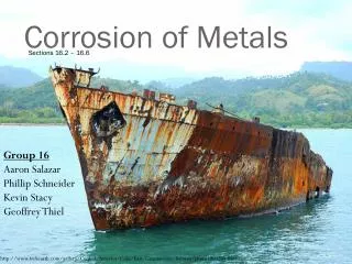
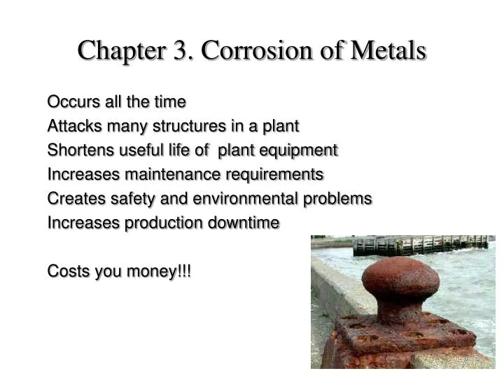
Occurs all the time Attacks many structures in a plant Shortens useful life of plant equipment Increases maintenance requirements Creates safety and environmental problems Increases production downtime Costs you money!!!. Chapter 3. Corrosion of Metals.

E N D
Occurs all the time Attacks many structures in a plant Shortens useful life of plant equipment Increases maintenance requirements Creates safety and environmental problems Increases production downtime Costs you money!!! Chapter 3. Corrosion of Metals
Corrosion causes catastrophic failures !! Corrosion caused leakage which triggered the fire that destroyed this Nypro Reactor
Chevron 2001 The leak caused by corrosion at this elbow started the fire that destroyed this refinery
TYPES OF CORROSION There are many different ways of looking at real cases of metallic corrosion: • low-temperature corrosion and high-temperature corrosion • dry corrosion and wet corrosion: atmosphere, industrial gases aqueous solutions, liquid chemicals • chemical corrosion and electrochemical corrosion • types of metals: steels, aluminium alloys, ceramics, etc. • types of environment: sulphuric acid, alkalis, marine, etc. One classification regards industrial metallic corrosion in 10 categories: • uniform attack • galvanic corrosion • crevice corrosion • pitting • intergranular corrosion • selective leaching • stress-corrosion cracking and corrosion fatigue • hydrogen damage • oxidation • high temperature corrosion
UNIFORM CORROSION uniform removal of metal over the entire surface • it is the most common type of corrosion; it is most metal-consuming • all metals are attacked by uniform corrosion • it could be either chemical or electrochemical • steady corrosion over the entire surface exposed to the corroding media • least objective in engineering design: easy testing, easy inspection, easy prediction of failure Uniform corrosion is dealt with most effectively by • proper selection of materials • application of protective coatings • addition of inhibitors • cathodic protection Question: do you know how the rate of uniform corrosion is determined? This is an important parameter for both the design and maintenance
corrosion products of the unprotected re-bars expend in volume and cause cracking to the concrete Coating holidays cause localised corrosion
GALVANIC CORROSION The corrosion of one metal caused by another in an electrochemical process driven by the potential difference between the two metals. In this process, the corrosion in one metal is accelerated (the anode) while in the other suppressed (the cathode) Three Essential Conditions • potential difference • presence of an electrolyte • electrical connection between the two electrodes Factors Influencing Galvanic Corrosion • potential difference: electromotive force (emf) of pure elements galvanic series of alloys • environment: electrolyte conductivity, temperature, etc. be aware that under certain environment conditions a galvanic coupling may reveres their cell potential difference: galvanised steel in hot water systems • cathode-to-anode area ratio • distance effect
Restoration of the Statue of Liberty in 1986, due to galvanic corrosion damage
Prevention Techniques • selecting metals of similar electrode potentials to minimise the driving force of the process • protection against moisture condensation to eliminate the chance of forming an electrolyte • insulation between dissimilar metals to avoid electrical connection • coating for electrical insulation or isolation of metal from electrolyte • installing a third metal which is anodic to both metals • designing for easy replacement of the anode metal or thicker section for longer service life Beneficial Applications of Galvanic Corrosion • Cathodic protection, sacrificial anode protection Galvanised steels:Zn coating is anodic to steel, act as a sacrificial metal • Cleaning silver blackened surfaces:silver sulphide rubbing with an abrasive?bad for silver plates Ag in Al pan: soda solution: cathodic reaction reduces silver sulphide to Ag
CREVICE CORROSION Crevice corrosion is a localised attack occurring within crevices or other shielded areas where a small volume of stagnated solution presents Mechanism In a seawater environment: H2O, O2, Na+ and Cl- Metal oxidises in balance with the reduction of oxygen: M M+ + e- (the anodic reaction) O2 + 2H2O + 4e- 4OH- (the cathodic reaction) M+ + OH- MOH Under stagnant conditions, the concentration of M+ increases due to a decreasing concentration of O2. The positively charged crevice attracts negatively charged ions: Cl- and OH-. Being a smaller ion, Cl- travels faster than OH- into the crevice. The increased concentration of Cl- in the crevicepromotes production of M +, encourages M+ + OH- MOH, and more hydrolysis of H2O, leading to increased [H+] concentration. Increased concentrations of [H+] and [Cl-] accelerate the corrosion crevice corrosion is self-catalytic.
Crevice corrosion on the face of a flange caused by absorbent gasket, also known as gasket corrosion Crevice corrosion is auto-catalytic Crevice corrosion of a bolt
Characteristics • crevices of the width of 25 - 100 m are most effective • • concentration of Cl- in a crevice is found to be 3-10 times higher than that in surrounding areas in a case of dilute neutral NaCl solution: pH value drops from 7 to 2-3. • • crevice corrosion is characterised by an initiation period with a very slow start and an ever-increasing corrosion rate. • • the oxygen reduction reaction provides cathodic protection in surrounding areas, making the attack inside the crevice very difficult to inspect. • • it occurs in many mediums and is most intense in Cl- solutions. • • metals and alloys having corrosion-resistant oxide films or passive layers are susceptible to crevice corrosion: • films destroyed by high concentration of Cl- and H+ • stainless steels and Al alloys are typical examples • Typical Conditions • holes on surfaces • gaps underneath bolt head or between lapping parts • porous mediums: gaskets, wood, fabrics, sand • deposition of dirt or corrosion product • water droplets, waterline • Example: an 18-8 stainless steel tank for a saline solution was safe in a dyeing plant; but when a stainless steel bolt accidentally fell to the bottom of the tank, rapid attack developed under the bolt after a brief period, causing leakage.
Minimising Crevice Corrosion • use welded butt joints instead of riveted or bolted joints • seal crevices: continuous welding/soldering • regular and thorough cleaning or complete draining to remove deposits or avoid stagnation • filter or screen flow to remove solids in suspension • use non-absorbent gaskets, such as Teflon, whenever possible. • use crevice corrosion resistant alloys Maximum crevice corrosion resistance is achieved in alloys of • a narrow active-passive transition • a small critical current density • an extended passive region Titanium and high nickel alloys are examples of such materials. Type 430 stainless steel has a large critical current density, a wide active-passive transition and a limited passive region. It is extremely susceptible to crevice corrosion. Stainless steels as a family are very poor in resisting crevice corrosion.
Minimising Crevice Corrosion – tutorial questions • Due to the similar mechanism many other forms of corrosion are also considered crevice corrosion. These include: • Deposition corrosion • Waterline corrosion • Inlet corrosion • Gasket corrosion • Droplet corrosion • Differential aeration corrosion • What are these forms of corrosion? • Why are they considered similar to crevice • corrosion? • How is crevice corrosion resistance • (or tendency) evaluated for materials? • What about pitting resistance? Most corrosion is found in the splash zone, where wet-dry conditions alternate
PITTING • Pitting is a highly localised form of corrosion. It is characterised by pits or holes of various sizes: • small diameters and depth-to-diameter ratio of >>1 • often in clusters • fail because of perforation with small weight loss • most destructive • very difficult to detect • difficult to evaluate by laboratory tests • develop and grow in the direction of gravity • undercut surface as they grow Corrosion pits
Factors Affecting Pitting • Solutions • solutions containing chloride or chlorine-containing ions: sea water hypochlorites (HClO3) have strong pitting tendencies; oxidising metal ions with chlorides are extremely aggressive pitters: • cupric (CuCl2) and ferric (FeCl3) chlorides • Flow • Pitting is associated with stagnant conditions. Increasing flow velocity decreases pitting attack. • Alloys • As a class, stainless steels are more susceptible to pitting corrosion than are any other group of metals or alloys. • Solution-quenched austenitic SS exhibit better pitting resistance. • Cold working increases pitting attack of 18-8 steels, preferentially on edges. • Surface finish affects pitting resistance. Polished surfaces are more resistant than etched or ground surfaces. • Cr, Ni, Mo and N as alloying elements increase pitting resistance of SS. • Type 316 SS is more resistant to pitting than type 304 due to the addition of 2%Mo. Type 304 is considered unsuitable for applications in seawater whereas type 316 is sometimes recommended. Ti has excellent resistance to pitting, owing to its protective film being inert to Cl- and H+.
The Mechanism The process of pitting corrosion consists of two stages: the initiation and the growth. Initiation: Pitting starts with an initiation period of very slow corrosion rate. Pitting selectively initiates at areas of surface irregularities chemical, microstructural, physical. • a surface scratch or other mechanically induced break • en emerging dislocation or slip step • a compositional heterogeneity such as an inclusion, segregate or precipitate The initiation of pitting is very fragile and young pits are unstable. Growth: Following the initiation, a pit grows at an ever-increasing rate with an identical mechanism to crevice corrosion. It is an autocatalytic process. The same mechanism implies that alloys that show pitting attach are also susceptible to crevice corrosion.
EROSION CORROSION • Erosion corrosion is a result of the combined effect of chemical attack and mechanical abrasion. • The Attack: • The damage appears as groves, waves or holes, following the direction of the flow. • • Typical conditions: • submarine propellers • interior of slurry pumps • exterior parts of high speed boats and ships • high flow rate pipelines • • Special locations: • elbows and junctions, extra angular acceleration • sudden reduction of pipe diameter, high velocity • sudden increase of pipe diameter, turbulence • valves, high velocity + turbulence • • Alloys: • Most alloys are susceptible to erosion corrosion, particularly those that have low hardness and rely on protective surface films for corrosion resistance, such as Al, Pb and Cu alloys, and stainless steels.
Liquid impingement and impingement erosion Erosion corrosion at pipeline elbow Solid erosion corrosion of impellers in slurry media
Factors Affecting Erosion Corrosion • Medium Many mediums can cause erosion corrosion. These include gases, aqueous solutions, organic systems, and liquid metals. Solid particles in suspension in fluid are most destructive by destroying surface films. • Velocity Increasing velocity generally increases erosion corrosion rate. There usually exists a critical velocity beyond which the rate of corrosion is suddenly increased. -laminar flow moving at a velocity removes metal ions from metal surface and break local equilibrium balance, encouraging further dissolution of metal -low flow velocity helps avoid stagnant conditions, replenish oxygen and bring inhibitors to metal surface, leading to a decrease in corrosion rate -corrosion tests under static or slow motion conditions often do not represent the real situation.
• Turbulence Turbulence provides a greater agitation of the fluid and greater mechanical impact to the surface of the metal. Instantaneous high pressure pulses associated with the formation and explosion of microbubbles cause most damage to metal surfaces. • Impingement Impingement create a local environment of very high velocity, very strong turbulence, and very high pressure pulses and thus is very destructive in causing erosion corrosion. • Cavitation Cavitation damage is a special form of erosion corrosion, commonly observed on components moving at very high velocities through fluid. It is caused by the formation and collapse of liquid vapour bubbles, which may create local pressure pulses as high as 400 MPa, causing local plastic deformation and destruction of surface films to the metal. Typical cases of cavitation damage: -leading edge of the wing of supersonic airplanes caused by rain droplets - leading edge of propellers of sea going vessels -body of high speed boats -liner on the coolant side of vehicle engines caused by vibration
Minimising Erosion Corrosion • Materials Solid solution hardening is effective in improving resistance to erosion corrosion. Solution hardening is more effective than other hardening methods in improving corrosion resistance is due to the fact that other methods tend to produce heterogeneous microstructure or cause mechanical instability to surfaces. - High silicon iron is an improvement to cast irons and it is widely used in severe erosion corrosion conditions, such as slurry carrying pipelines. - Alloying with noble metals to be inherently more resistant to corrosion 80%Ni-20%Cr alloy ferritic stainless steels (80%Fe-20%Cr) - Alloying to form more stable and impermeable surface films 316 stainless steel to improve 304 aluminium brass to improve Cu-Zn brass - Stainless steel is considered to have the greatest resistance towards cavitation Shape memory alloys are excellent in resisting cavitation, due to their ability to deform non-destructively during impact.
• Design • Erosion corrosion is closely related to the structure of a system and the flow pattern of the liquid; thus, many erosion corrosion situations may be avoided or minimised by proper design. • Increasing tube diameter to reduce flow velocity and ensure laminar flow • -Increasing tube diameter to reduce flow velocity and ensure laminar flow • -Using streamline bends and expanded junction section to minimise impingement effect • -Lining with second metal at high risk locations (galvanic corrosion !!!) • -Easy to replace • -Protruding pipe ends at inlet and out let, delivering turbulence away from the vessel wallinto the middle of liquid. • -Very smooth surface to minimise the chance of vapour nucleation as against cavitation • • Environment • Settling and filtering to remove solids in suspension are helpful. Inhibitors may also be added to the liquid. Decreasing temperature always reduces the rate of corrosion. • • Surfacing • Some surface coatings are effective to prevent other forms of corrosion, but may not have satisfactory mechanical properties to stand against erosion corrosion, particularly when a heavily suspended slurry solution is involved. Hard facings, welded overlays and replaceable inserts are widely used. proper design is the most effective way of preventing erosion corrosion
INTERGRANULAR CORROSION Intergranular corrosion is a localised corrosion that occurs preferentially along grain boundaries inside a metal. • Grain Boundary Attack Grain boundary regions are generally subjected to a higher degree of corrosion, because of the relatively higher free energy state, chemical segregation and impurity concentration. However, in most cases grain boundary corrosion does not impose a serious problem to the performance of a structural component. • Sensitisation of Austenitic Stainless Steels Austenitic stainless steels tend to form carbide precipitates (Cr23C6) along grain boundaries at 400-850 °C, causing a local depletion of Cr. The sensitised regions are anodic to the grains and are attacked preferentially. A common cause of sensitisation is welding, known as weld decay. Common heat treatments of austenitic stainless steels: (i)stress relieving at 350-450 °C to avoid sensitisation (ii)solution annealing at 1000-1100 °C followed by quenching to eliminate the effect of sensitisation; more problems with cast austenitic stainless steels
The problem of weld decay may be avoided by using: - L grades: 304L, 317L, 316L: <0.03%C , standard 18-8 steels: 0.06-0.15%C - Stabilisers: strong carbide forming elements: Nb, Ta (type 347), Ti (type 321) - Electric arc welding instead of flame welding: more rapid heating cycle, narrower heat affected zone, lower tendency to form carbides in HAZ - Laser cutting instead of oxy-flame cutting • Other Alloys Susceptible to Sensitisation Some high strength Al alloys are also susceptible to sensitisation. For example, the strengthening precipitates CuAl2 in Al-Cu alloys cause local depletion of Cu, reducing their corrosion resistance. Acceperated grain boundary corrosion due to Cr depletion caused by formation of Cr carbides Heat affected zones provide a condition for SS sensitisation Fusion cutting is another case
SELECTIVE LEACHING Selective leaching, also known as dealloying and parting, is the selective preferential removal of one elemental spices in an alloy system. dezincification of yellow brass dealuminification of aluminium bronze graphitisation of grey iron dechrominification • Dezincification zinc dissolves in pure water by a hydrolytic reaction. Better resistance to dezincification: red brass: 85-15%Zn alloying: "inhibitors", such as Sn, As and P Al bronze and Si bronze are attacked by selective leaching Al, Si and Zn are anodic to Cu
• Graphitisation Graphitisation is the selective removal of iron from the surface of grey cast iron due to a galvanic reaction between the graphite and iron. It is the most costly damage large-diameter underground water mains. - Graphite is cathodic to iron, forming excellent galvanic cells - Moist soil under the ground and aqueous solution it carries inside provide the environment for selective leaching - Earth movement may cause failure as a result of reduced strength - Use of nodular or malleable iron is effective in avoiding graphitisation Dezincified yellow brass showing red Cu colour
STRESS CORROSION CRACKING The Attack Stress corrosion cracking (SCC) is a cracking failure of materials caused by the combined action of tensile stresses and corrosive environments. SCC occurs to many different materials, including plastics, Al alloys, Cu alloys, Mg alloys, carbon steels, stainless steels, Ti It occurs only with specific material-environment combinations: stainless steels in 50-60 °C chloride-containing solutions carbon steels in caustic solutions Al alloys in chloride solutions Cu alloys, particularly brasses, in ammonia atmosphere The environments in which SCC occurs sometimes are not highly corrosive to the metals in question. When SCC happens the metal may be virtually unattacked over most of its surfaces. The stress that induces SCC is also often very much lower than the failure stress of the metal. It is the combination of the two that causes the attack. Morphology of cracks Wedging effect of corrosion products Intergranular and transgranular cracks
Factors Affecting Stress Corrosion Cracking • Stress: • residual stresses: welding, cold working, heat treatment and casting • appliedstresses: gravitation, mechanical assembling stresses, temperature variation, etc. • a critical stress seems to exist for SCC for each metal-environment combination • Time • Materials fail by SCC in brittle fracture manners - corrosion is responsible for nucleation of cracks and failure occurs by mechanical cracking. • short time SCC tests • decreasing stress and temperature increases failure time • Metallurgical Factors • Generally speaking, pure metals have lower tendency towards stress corrosion cracking than alloys. Single phase structure better than multiphase structures. Segregation of precipitates raises the susceptibility to stress corrosion cracking. However, a soft phase inclusion, such as ferrite domains in austenite stainless steel matrix, may relax the stress concentration at crack tips and slow down their propagation.
Environment • No general rules to what environments cause SCC • Specific metal - environment combinations • Refer to the list of established data for known combinations • Conduct new tests for combinations Cracks may propagate in intergranular or transgranular manner. Chloride SCC. SCC always occurs at the tensile stress site
The Process of Stress Corrosion Cracking • unclear mechanism - complex interplay of metal, environment, stress states and interface properties • Initiation • Corrosion is the primary reason for crack initiation - cracks are observed to start at the base of a pit. • A tensile stress assists breaking up protective films and enhance the elastic energy of surface atoms. • Propagation • In the intermediate stages, stress corrosion cracking proceeds by the conjoint action of stress (concentration) and corrosion at crack tips. Cracks have been observed to propagate in discontinuous steps, emitting acoustic waves when jumping. The contribution of corrosion to crack propagation is evident in experiments when acoustic waves are stopped at the application of cathodic protection and resumed after the removal of the cathodic protection. • preferential attack at crack tips: • local plastic deformation, increased defect density, emerging slip steps, decreased resistance to chemical attack • Cracking • The final failure caused by unstable propagation of cracks is basically a mechanical process. However, the presence of corrosive chemicals and water molecules at the crack tips lowers the critical stress for cracking.
Summary Stress corrosion cracking is an electrochemical-mechanical process. It initiates at small but chemically active areas such as a stress induced film rupture, a high energy grain boundary, and chemical segregation sites. Stress corrosion cracks propagate in discontinuous steps. The slow motion of corrosion builds up stress concentration at a crack tip until a critical moment when the crack propagate to a new location and stopped when the stress concentration is relaxed. Stress corrosion cracks may follow intergranular and transgranular paths. In materials having complex slip systems or high stacking-fault energies, cracks propagate along intergranular paths. The role of corrodant in the mechanism of stress corrosion cracking is the least understood.
Prevention Avoid dangerous metal-environment combinations by using a different metal. Carbon steels sometimes are used in preference to stainless steels due to their higher resistance to stress corrosion cracking. Inconel is used to replace type 304 SS for the same reason. Eliminate the tensile stress component whenever possible. More than often a tensile stress is from residual sources; thus stress relieving heat treatment is commonly recommended. Furthermore, creating a compressive surface residual stress condition is highly effective in suppressing stress corrosion cracking. A compressive surface stress state may be achieved by various means including thermal treatment, blasting, ion implantation. Reduce the corrosivity of environment, such as to change the pH of a fluid, to eliminate oxygen or chloride from a solution. Inhibitation, cathodic protection and design modification may also render the environment less harmful. Cathodic protection is effective. It may be applied either with an external power supply or consumable anodes. Precautions must be taken when applying cathodic protection to guard for hydrogen embrittlement.
Corrosion Fatigue • The presence of a corrodant, or the action of corrosion, tends to reduce the fatigue life, or decreases the fatigue limit, of a metal. • Little is known about corrosion fatigue beyond the knowledge of stress corrosion cracking. • Corrosion fatigue is characterised by transgranular cracks that do not show much branching. The final cracking is largely a mechanical process. • Factors Affecting Corrosion Fatigue • Fatigue life in the case of pure mechanical loading is determined by the number of cycles; the effect of cycling frequency is negligible. In the case of corrosion fatigue, however, stress-cycle frequency has a strong influence on the fatigue life of a metal. Corrosion fatigue is most pronounced at low stress frequencies. Low frequencies allow a better contact of corrodant to the metal at crack tips. • Prevention • In addition to those applied to stress corrosion cracking, vibration should clearly be avoided to prevent corrosion fatigue, by, for instance, proper designs.
HYDROGEN DAMAGE • Hydrogen in environment is damaging to metals • Damage is associated with hydrogen absorption • Forms of damage: embrittlement, blistering & decarburisation • Sources of atomic hydrogen: • corrosion process • application of cathodic protection • welding • electrolysis & electroplating • Hydrogen Blistering • Hydrogen blistering is caused by the formation of micro-bubbles of high pressure hydrogen gas inside the metal • The most damaging fact is that the equilibrium pressure between H2 and H is very high - several 100,000 atm, sufficient to rupture any known engineering material. • Hydrogen blistering is most prevalent in petroleum industry. It occurs in storage tanks and in refining processes.
Hydrogen Embrittlement • Hydrogen embrittlement is the brittle cracking of metals caused by hydrogen absorption. The actual embrittling mechanism is not clear. • Ti alloys: formation of brittle hydrides • Irons & steels: interaction of H & crack tips • Different from SCC: cathodic current suppresses SCC but encourages hydrogen embrittlement • Hydrogen embrittlement is a more serious problem in high strength materials: • - HSLA steels • - high strength grades of carbon steels • - Ti alloys • - Cu alloys
Prevention • "Clean" steels: • rimmed steels: high % microvoids • killed steels: voids-free structure • Coating & lining: • impervious to hydrogen penetration • electroplating, cladding with ASS or nickel • porous materials: brick lining • Resistant alloys: • Ni-containing steels & Ni alloys • low diffusion rate of H in Ni • Baking: • absorption of H in metals is reversible • baking at 100-150°C removes dissolved H in steels • Process control: • pickling, plating & welding • Low-H or H-free welding techniques
Decarburisation & Hydrogen Attack • Removal of C in C-containing alloys at high T: • [C] + 4[H] = CH4 • CH4 formed in microvoids exerts a high pressure to the matrix of steels, causing embrittlement – known as hydrogen attack • Hydrogen attack occurs in • - petrochemical plants • - oil refineries • - processing lines for ammonia & methanol synthesis • - conventional power stations • Environmental Effect • Hydrogen attack occurs in carbon steels at 250 - 600 °C with critical hydrogen partial pressures of 1 -75 MPa. Increasing temperature decreases the critical hydrogen partial pressure required for the attack. At temperatures below 200°C, carbon steels are not attacked by hydrogen gas even under relatively high pressures.
Metallurgical Factors • The sensitivity of carbon steels to hydrogen attack increases with carbon content: • - commercial pure iron (0.004%C) resisted attack at 540°C & 4.8 MPa for 500 hrs • - steel (0.009%C) was attacked under the same conditions • Alloying with carbide-forming elements (Ti, V, Cr, Mo and W) improves resistance to hydrogen attack. These elements stabilise C in the matrix, mostly by forming complex alloy carbides, such as (Fe,M)3C or M7C3. • Processing • - Cold worked steels embrittle easily in high-T, high-P hydrogen • - Surface stresses accelerate H absorption and cause hydrogen attack • - HAZ in a weldment is more susceptible to hydrogen attack • - Quench and tempered steels are more resistant than normalised ones - Spheroidising improves resistance to hydrogen attack
OXIDATION Reaction between a metal and O2 at the absence of water. Dry oxidation is only a process of appreciable rate at elevated temperatures for most metals Pilling-Bedworth Ratio It is suggested that oxidation resistance of a metal depends on the properties of the metal oxide on the surface, as determined by the Pilling-Bedworth Ratio: PB ratio = PB ratio ~ 1 gives good oxidation resistance Requirements on protective film: - good adherence, coherent to base metal - good mechanical properties: strength, ductility and toughness, no rupture under applied or thermal stresses - high melting temperature - similar thermal expansion coefficient to metal - low diffusion coefficient for oxygen and metal ions
Electrochemistry of Oxidation Oxidation process of metals in gaseous oxygen is effectively an electrochemical process rather than a simple chemical reaction, in analogy to aqueous galvanic process, for example: Cu + O2 = CuO Anodic reaction at metal-scale interface: Cu = Cu2+ + 2e- Cathodic reaction at scale-gas interface: O2 + 2e- = O2- Most metal oxides conduct electrons and ions to some extent
Morphology of Oxides Diffusion of either metal ions or oxygen ions through the oxide controls the oxidation rate Fe, Ni, Cu, Cr, Co: oxides grow preferentially at the scale-gas interface by outwards cation diffusion certain protection of the scale Ti, Ta, Zr, Hf: oxides grow inwards at the metal-scale interface, non-protective due to scale fracturing Oxidation Rate Controlling factor: conductivity of oxide Anion deficient oxides: n-type oxides Cation deficient oxides: p-type oxides Alloying with higher valence metals reduces anion vacancy concentration of n-type oxides & reduces the rate of diffusion-controlled oxidation Alloying with lower valence metals reduces cation vacancy concentration of p-type oxides & reduces the rate of diffusion-controlled oxidation
Oxidation Kinetics Different metals show different oxidation kinetic behaviour - Linear: W = kt metals having non-protective surface films Na, K PB ratio ~0.5 Ta, Nb PB ratio ~2.5 - Parabolic: W2 = kt + C metals having protective surface films Fe, Co, Cu, Ni - Logarithmic: W = klog(Ct + A) empirical observation thin oxide layers at low temperatures Al, Cu, Fe - Catastrophic: oxidation with continuously increasing rate ignition and self-sustained combustion of metals Mg, Al (powder), Zn
Oxidation Resistance of Fe-Ni-Cr Alloys Fe, Ni and Co exhibit only moderate oxidation resistance. Alloying with Cr, Si and Al enhances their resistance. Fe-Ni-Cr alloys are the most commonly used alloys for general purpose high temperature oxidation resistance applications, largely due to their relatively low costs, moderate oxidation resistance, and good mechanical properties