Download
1 / 6
60 likes | 220 Views
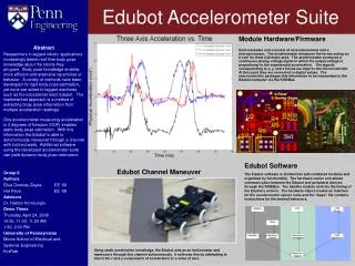
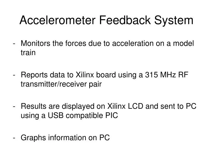
Accelerometer Feedback System. Monitors the forces due to acceleration on a model train Reports data to Xilinx board using a 315 MHz RF transmitter/receiver pair Results are displayed on Xilinx LCD and sent to PC using a USB compatible PIC Graphs information on PC. Train Mounted

E N D
Accelerometer Feedback System • Monitors the forces due to acceleration on a model train • Reports data to Xilinx board using a 315 MHz RF transmitter/receiver pair • Results are displayed on Xilinx LCD and sent to PC using a USB compatible PIC • Graphs information on PC
Train Mounted PIC and Sensor RF Receiver System Overview 315MHz Link UART0 Wired Connection Xilinx Board UART2 Wired Connection PC USB PIC USB Link
PIC Specific Hardware • Train Mounted PIC • 18LF1220 • Low cost, 3.3 Volts, 18 Pin DIP, 8 MHz Internal Oscillator • Uses 2 Channel ADC • 2400 baud UART • USB PIC • 18f4550 • 40 Pin DIP, 20 MHz Crystal • High Speed USB 2.0 • 19200 baud UART
Xilinx Software • Three UARTS • RF Receiver - Captures sensor readings from train mounted PIC • USB Communication - Sends most recent sensor readings upon request - Gets alarm settings • Accessory Communication - Alerts extra boards when alarm condition is reached • LCD - Shows sensor readings and current alarm status
Future Improvements • Upgrade transmitter/receiver • 2.4 GHz results in less noise • Supports up to 250K baud • Change DIP to SMT components • Decreases board size • Lowers cost of manufacturing • Move Xilinx functionality to PIC 18F4550 • Greatly reduces cost and complexity