Download
1 / 20
200 likes | 297 Views
Safe Allocation of Avionics Shared Resources. Gérard Bel, Pierre Bieber, Frédéric Boniol, Charles Castel, Laurent Sagaspe. Overview. Integrated Modular Avionics (IMA) Potential benefits and drawbacks Terrain Following/Terrain Avoidance Function IMA Resource Allocation Process

E N D
Safe Allocation of Avionics Shared Resources Gérard Bel, Pierre Bieber, Frédéric Boniol, Charles Castel, Laurent Sagaspe
Overview • Integrated Modular Avionics (IMA) • Potential benefits and drawbacks • Terrain Following/Terrain Avoidance Function • IMA Resource Allocation Process • Failure Propagation Modelling • Safety Requirements Validation • Independence Constraint Identification • Allocation Constraint Solving • Multi-domain Resource Allocation • Real-Time Performances • ElectroMagnetic Interference
Integrated Modular Avionics – 1/2 • Computing and Communicating resources shared by several avionics applications • Civilian aircrafts: B777, A380, B787,... • Standards : ARINC 664 (AFDX), ARINC 653 (Real-time OS) • Military aircrafts : F22, Gripen, A400M, ... • Standards: ASAAC • Potential Benefits • Decrease weight of aircraft, maintenance simplification, ... • Potential Drawbacks • One shared resource failure could lead to the failure of several applications • Development is more complex as new teams participate in it
IMA team Application Designer Safety Analyst Failure Propagation Model Safety Requirement Validation Independence Constraints Identification Integrated Modular Avionics – 2/2 • Resource Allocation Process Can we implement these functions on this architecture and enforce these requirements ? Can we implement these functions on the IMA architecture and enforce their requirements ? The functions can be implemented on the architecture and enforce their requirements provided that these allocation constraints are enforced Allocation Constraint Solving This is an allocation of resources to your functions such that their requirements are enforced
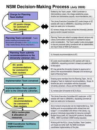
Computation of Vertical acceleration Climb alarm Consolidated Roll angle Terrain Following/Terrain Avoidance • Navigation in the vertical plane
Terrain Following/Terrain Avoidance Function Tasks and Data flows Attributes Worst Case Transmission/Execution Time, Period Failure Mode, Severity … Avionics architecture • Interconnected resources • Virtual Communication and Computing resources • Real Bus, Switch, CPU, … • Zones and routes in the Aircraft Function and Architecture Description
Overview • Integrated Modular Avionics (IMA) • Potential benefits and drawbacks • Terrain Following/Terrain Avoidance Function • IMA Resource Allocation Process • Failure Propagation Modelling • Safety Requirements Validation • Independence Constraint Identification • Allocation Constraint Solving • Multi-domain Resource Allocation • Real-Time Performances • ElectroMagnetic Interference
Failure Propagation Modeling in AltaRica What is Altarica ? • AltaRica model is a set of interconnected nodes • Node has 3 parts : variable declarations, transitions and assertions codedrawingequivalent automaton Node block flow A,R : bool : in; I : {ok,erroneous,lost} : in; O : {ok,erroneous,lost} : out; state S : {ok,erroneous,lost}; event loss, error; trans S=ok |- loss -> S := lost; S=ok |- error -> S := erroneous; assert O = case{S=ok and R and A: I, S=erroneous and R and A :erroneous, else: lost}; init S := ok; law extern <event loss>=«constant 1e-4» <event error>=«constant 1e-5» edon S=ok O = if {R and A } then I else lost loss (constant 1e-4) error (constant 1e-5) S=erroneous O = erroneous S=lost O = lost
TF/TA model was built using predefined nodes in an Altarica Library OCAS Tool (Dassault Système) Model Edition Interactive Simulation Safety Tools Used for Falcon 7X certification Failure Propagation Model – 2/2
Safety Requirements – 1/2 • Qualitative Safety Requirement: • « No single failure shall cause an undetected erroneous vertical acceleration » • In the TF/TA model, an erroneous vertical acceleration is undetected if: VertAccel.O=erroneous and ClimbAlarm=false • We are interested in cases where it remains undetected during three consecutive time steps: FC = VertAccel.O=erroneous and ClimbAlarm=false and X (VertAccel.O=erroneous and ClimbAlarm=false) and XX (VertAccel.O=erroneous and ClimbAlarm=false) The TF/TA model should enforce: (F FC) => at_least_ 2_failures
Safety Requirements - 2/2 • Safety Assessment Techniques • OCAS Fault-Tree generation • The fault tree can be exported to other tools (Simtree, Arbor,...) to compute minimal cut sets and probabilities • OCAS Sequence Generator • Automatic generation of sequence of failure that lead to the violation of Safety Requirements • Limit on the number of failures to be considered • Cadence Labs SMV Model-checker • Translation from Altarica to SMV • Requirement proved by SMV model-checker or Counter-example generated • Each technique has an application domain • Fault Tree generation: static systems and instantaneous failure conditions • Sequence generation: dynamic systems and instantaneous failure conditions • Model-checking: dynamic systems and temporal failure conditions
Independence Assumptions 1/2 • Assumptions are needed to prove that Safety Requirements hold • The proof is split into two parts Scenario Search: F FC => Scenarii Assumptions: Independence_Assumptions => at_least_2_failures • Scenarii : (F VertAccCmp.fail_error & F ClAlarmCmp.fail_lost) or (F Radar.fail_error & F ClAlarmCmp.fail_lost) or ... • Independence_Assumptions: (F VertAccCmp.fail_error & F ClAlarmCmp.fail_lost) => at_least_2_failures and (F Radar.fail_error & F ClAlarmCmp.fail_lost) => at_least_2_failures and ...
Independence Assumptions - 2/2 • Segregation constraints are extracted from the independence assumptions: • Example: • tasks VertAccCmp and ClAlarmCmp shall fail independently. They shall not share computation resources. • Example: • Dataflows VerAcc and Alarm should fail independently. They should not share communication resources • Alternative approach for identification of segregation constraints: • Use safety architecture patterns: Command and Monitor architecture • Command channel : Navigation,Radar, TFTAPanel, VertAccelComp • Monitor channel: RA, Navigation, Emergency • Command and Monitor channels shall be segregated: " Navigation,Radar, TFTAPanel, VertAccelComp" and " RA, Navigation, Emergency" should fail independently.
Allocation Constraints • Formalisation of allocation constraints • {0,1} linear inequalities. • Variables : • allotc(task,cpu) : {0,1} • allodb(data,bus) : {0,1} • connected(cpu,bus) or connected(bus,cpu) : {0,1} • Inequalities • Any task has to be allocated to one and only cpu allotc(t,c1) +…+ allotc(t,cn) = 1 • Two independent tasks should not be allocated to the same cpu allotc(t1,c) + allotc(t2,c) + indep(t1,t2) < 2 allod(t1,c) allod(t2,c) si indep(t1,t2) = 1 • A connection (C,B) is used if there exists a data flow D and its producing task T such D is allocated to B and T is allocated to C. • Criterion • Minimise the number of used connections
Generation of constraints Call to solvers (ILOG solver, satzoo) Visualisation of allocations Tool Support for Constraint Solving Goal= 8
Overview • Integrated Modular Avionics (IMA) • Potential benefits and drawbacks • Terrain Following/Terrain Avoidance Function • IMA Resource Allocation Process • Failure Propagation Modelling • Safety Requirements Validation • Independence Constraint Identification • Allocation Constraint Solving • Multi-domain Resource Allocation • Real-Time Performances • ElectroMagnetic Interference
IMA team Real-Time Engineer Application Designer EMI specialist Multi-Domain Resource Allocation • Resource Allocation Process functions, requirements architecture functions , requirements Safety Analyst allocation constraints allocation Allocation Constraint Solving
Real-Time Performance Viewpoint Schedulabilty Analysis, example: Necessary Condition : Si Ci/Ti< 1 Sufficient Condition for RMA: Si Ci/Ti< 0.69 Tasks : execution delays for individual tasks (period enforcement) and for groups of tasks (end-to-end latency) Resources: use indicators • Schedulability Analysis(holistic model, worst case ), ILOG solver • Discrete Event Simulation (generalized model), Hyperformix • Scheduling constraints are extracted: • « allocation of tasks to the resources shall not overload the resources » • « allocation of data-flows to communication resources shall enforce end-to-end latencies »
ElectroMagnetic Interference Viewpoint • Quantitative Requirement: • « The probability that dataflow D is lost/erroneous due to ElectroMagnetic Perturbation Is smaller than 10-x» • Abstract stochastic model of electromagnetic interference • --> computation of an additive measure of EMI perturbation for each zone and route • Place and routing constraints are extracted: • “Communication resource Bus1 should be routed in routes that have less that Y abstract EMI perturbation units”
Conclusion • The proposed approach is consistent with industrial practices • New safety analysis required for IMA design • allocation generation is not used by now • Further Work • The approach could also be applied to integrate several applications into a common avionics architecture • Associate constraints with each application • Model reuse • Use libraries of components and patterns to limit the time/effort to produce viewpoint models • Use standard modelling notations: COTRE, AADL,…