Download
1 / 40
400 likes | 574 Views
JTAG environment Full Chip testing. Test Logic Architecture. In the following presentation we will discuss the needs and means for the creation of a JTAG dft environment. Within the chip Outside of the chip. The environment is designed for: RTL block testing

E N D
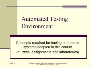
Test Logic Architecture • In the following presentation we will discuss the needs and means for the creation of a JTAG dft environment. • Within the chip • Outside of the chip • The environment is designed for: • RTL block testing • Creating the patterns for the testers • Gate-level testing • FPGA testing • Silicon testing
Test Logic Architecture • Basically making a complicated testing seem so simple from the outside
Test Logic Architecture • The following elements shall compose the test logic architecture within the chip: • A TAP • A TAP controller • An instruction register • A group of test data registers
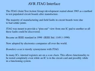
Test Access Port - TAP • The TAP is a general-purpose port that can provide access to many test support functions built into a component. • It is composed as a minimum of the three input connections and one output connection. • An optional fourth input connection provides for asynchronous initialization.
TAP connections • Test clock input (TCK) • Provides the clock for the test logic. • Stored-state devices in the test logic shall retain their state indefinitely when the signal applied to TCK is stopped at 0. • Test mode select input (TMS) • This signal is decoded to the TAP controller to control test operations. • Shall be sampled on the rising edge of TCK. • Test data input (TDI) • Serial test instruction and data. • Shall be sampled on the rising edge of TCK.
TAP connections continue… • Test data out (TDO) • Serial output for test instruction and data. • Changes in the state of the signal driven through TDO shall occur only on the falling edge of TCK. • Test reset input (TRST*) • Provides for asynchronous initialization of the TAP controller. • Active low.
Interconnection of components compatible with the standard • The figures on the next slide illustrate three alternative board-level interconnections of components conforming to IEEE Std 1149.1-2001 standard.
Interconnection of components compatible with the standard Serial connection using one TMS signal Connection in two paralleled serial chains Multiple independent paths with common TMS and TCK signals
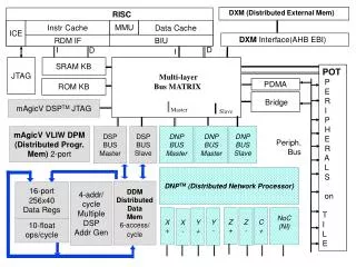
Test Logic Architecture Top level design - figures Clock and/or controls A conceptual schematic of test logic
Test Logic Architecture • The following elements shall be contained in the test logic architecture within the chip : • A TAP • A TAP controller • An instruction register • A group of test data registers
TAP Functional Overview • Compiles with the IEEE Std 1149.1 (“JTAG”) test architecture standard • additionally provides access to most of the full chip testability features • provides not only a customer-visible feature of the chip but also provides crucial proprietary functionality for silicon debug and production testing
Inside the Chip JTAG FSM • The JTAG commands are 6 bit words chosen according to the IEEE standard and the test you want the JTAG to cover. For example: • The controller must implement the IEEE standard FSM. For example: • Using the JTAG commands we issue instructions to the correct test/action we want to activate. • BS,BIST,DAT and so on…
The TAP controller The TAP state machine
The TAP controller • The TAP controller is a synchronous finite state machine that responds to changes at the TMS and TCK signals of the TAP and controls the sequence of operations of the circuitry. The TAP state machine
The TAP controller • All state transitions of the TAP controller shall occur based on the value of TMS at the time of a rising edge of TCK. • Actions of the test logic (instruction register, test data registers, etc.) shall occur on either the rising or the falling edge of TCK in each controller state. The TAP state machine
The TAP state machine • Contains • Reset state • Run-test/idle state • Two major branches • Access to the TAP instruction register • Access to one of the TAP/core data registers • TMS pin is used as the controlling input. The TAP state machine
The TAP state machine • Test-Logic-Reset • Test logic disabled • Normal operation of the processor can continue. • Enters this state: • When the TMS input is held active for at least five clocks. • When TRST_N is pulled active. • Upon power-up. The TAP state machine
The TAP state machine • Run-Test/Idle • The idle state of the TAP controller. • The contents of all test data registers retain their previous values. • Self tests may run. • Shift-DR-Scan • Temporary controller state. • Shift-IR-Scan • Temporary controller state. The TAP state machine
The TAP state machine IR branch • Capture-IR • The shift register contained in the instruction register loads a fixed value. (two lsb are 01) • Test data registers selected by the current instruction retain their previous state. • The instruction does not change. The TAP state machine
The TAP state machine IR branch • Shift-IR • The shift register contained in the Instruction Register is connected between TDI and TDO and is shifted one stage toward its serial output on each rising edge of TCK. • The output arrives at TDO on the falling edge of TCK. • The current instruction does not change in this state. The TAP state machine
The TAP state machine IR branch • Exit1-IR • a temporary state. • TMS held high – the controller enters Update-IR which terminates the scanning process. • The current instruction does not change in this state. • Pause-IR • Allows shifting of the Instruction Register to be temporarily halted. • The current instruction does not change in this state. The TAP state machine
The TAP state machine IR branch • Exit2-IR • a temporary state. • TMS held high – the controller enters Update-IR which terminates the scanning process. • The current instruction does not change in this state. The TAP state machine
The TAP state machine IR branch • Update-IR • The instruction which has been shifted into the Instruction Register is latched onto the parallel output of the Instruction Register on the falling edge of TCK. The TAP state machine
The TAP state machine DR branch • Capture-DR • Data may be parallel-loaded into test data registers selected by the current instruction (on the rising edge of TCK). • The current instruction does not change in this state. The TAP state machine
The TAP state machine DR branch • Shift-DR • The Data Register connected between TDI and TDO as a result of selection by the current instruction is shifted one stage toward its serial output on each rising edge of TCK. • The output arrives at TDO on the falling edge of TCK. • The parallel, latched output of the selected Data Register does not change while new data is being shifted in. The TAP state machine
The TAP state machine DR branch • Exit1-DR • a temporary state. • TMS held high – the controller enters Update-DR which terminates the scanning process. • The current instruction does not change in this state. • Pause-DR • Allows shifting of the Instruction Register to be temporarily halted. • The current instruction does not change in this state. The TAP state machine
The TAP state machine DR branch • Exit2-DR • a temporary state. • TMS held high – the controller enters Update-DR which terminates the scanning process. • The current instruction does not change in this state. The TAP state machine
The TAP state machine DR branch • Update-DR • Data from the shift register path is loaded into the latched parallel outputs of the selected Data Register (if applicable) on the falling edge of TCK. • This (and Test-Logic-Reset) are the only controller states in which the latched paralleled outputs of a data register can change. The TAP state machine
Test-Logic-reset Run-Test/Idle Select-DR-Scan Select-IR-Scan Capture-IR Shift-IR Exit1-IR Pause-IR Exit2-IR Update-IR Test logic operation Instruction scan
TAP registers The instruction register • Allows an instruction to be shifted into the design. • The instruction is used to select the test to be performed or the test data register to be accessed or both.
TAP registers The instruction register • This register consists of 6 bit shift register and the actual instruction register. • The parallel output of the TAP instruction register goes to the TAP instruction decoder . Operation of the TAP Instruction register
TAP registers The instruction register • In Capture-IR, the shift register portion of the instruction register is loaded in parallel with the fixed value “NOP”. • In Shift-IR, the shift register portion of the instruction register forms a serial data path between TDI and TDO. • In Update-IR, the shift register contents are latched in parallel into the actual instruction register.
The chip Top • Every Chip has a Top layer which contains all it’s IO pins (functional and testing) • The IO pins change their functionality from one feature to another. • In order to test the full chip we wrap this top with our own new top – AV top. Where we can control the JTAG IO pins and check the other IO pins
AV Top AV Top IO pins TCK TMS TDI TDO
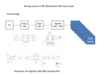
Chip external dft environment Chip_dft Jtag_stub dft_utils dft_straps dft_signals dft_tests basic dft operations: Writing a JTAG command, reading the output … Different utils needed Strap utils: powering up, z straps, clock bypassing … Connecting the signals threw Hw paths The tests!! Block/FC tests
Creating the patterns • After testing and approving the validity of the design on RTL we create patterns of 1 & 0 for each pin in the proper time. • We use the patterns for the Gate level testing and the silicon debug. TDI: 800ns – 1 850ns – 1 870ns – 0 ….
Testing the Gate level & silicon • Using the JTAG device along with the patterns as inputs for the 4 (or 5) access ports for before and after silicon validation.