Download
1 / 34
340 likes | 565 Views
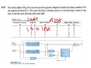
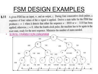
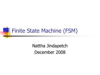
FSM 的设计: Mealy 机. 设计要点: 用输入和状态控制进程; 用 case 语句分别选择每一个状态; 用 if 语句确定输入条件,指定相应的下一状态和输出值; 输出立即赋值(使用一个进程); 状态等待时钟条件满足再进行赋值(使用另一个进程);. Mealy 机设计:例 1. 例 Mealy 状态机设计 该状态机具有 4 个状态,输入 x ,输出 z ;状态转换图如下所示;. Mealy 机设计:例 1. library ieee; use ieee.std_logic_1164.all; entity mealy is

E N D
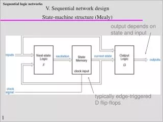
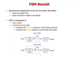
FSM的设计:Mealy机 设计要点: 用输入和状态控制进程; 用case语句分别选择每一个状态; 用if语句确定输入条件,指定相应的下一状态和输出值; 输出立即赋值(使用一个进程); 状态等待时钟条件满足再进行赋值(使用另一个进程);
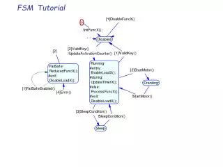
Mealy机设计:例1 例Mealy状态机设计 该状态机具有4个状态,输入x,输出z;状态转换图如下所示;
Mealy机设计:例1 library ieee; use ieee.std_logic_1164.all; entity mealy is port(x,clk: in std_logic; z: out std_logic); end mealy; architecture beh of mealy is type state is (s0,s1,s2,s3);--设置状态类型 signal current_state,next_state: state; --现态与次态 begin
Mealy机设计:例1 aaa:process(current_state,x) --决定次态和输出 begin case current_state is when s0=> if x='0' then z<='0';next_state<=s0; else z<='1';next_state<=s2; end if; when s1=> if x='0' then z<='0';next_state<=s0; else z<='0';next_state<=s2; end if;
Mealy机设计:例1 when s2=> if x='0' then z<='1';next_state<=s2; else z<='0';next_state<=s3; end if; when s3=> if x='0' then z<='0';next_state<=s3; else z<='1';next_state<=s1; end if; end case; end process aaa;--这个进程与时钟无关
Mealy机设计:例1 sync:process --将现态转移为次态 begin wait until clk'event and clk='1'; current_state<=next_state; end process sync; --这个进程受时钟控制 end beh;
计数器(counter)设计 计数器也称为分频器,是数字电路中的基本时序模块; 计数器通常以clk信号为基本输入,对输入信号进行计数,在clk每个周期中改变一次计数器状态,状态可以输出; 经过n次计数后,计数器将回到初始状态,并给出进位输出信号;
计数器(counter)设计 计数器的VHDL设计可以采用两种方式: 1 采用二进制串设置状态,指定循环的起点和终点,在时钟触发条件下对状态进行加1或减1运算,使状态顺序变化; 2 采用结构设计方式,先形成小型计数器,再扩展形成大型的计数器。
计数器的行为设计:74163 4位二进制加法计数器74163 p.708 表8-14 具有同步复位,同步置数和进位控制功能; 采用unsigned数据类型进行设计; library ieee; use ieee.std_logic_1164.all; use ieee.std_logic_arith.all;
计数器的行为设计:74163 entity k74163 is port ( clk,clrl,ldl,enp,ent: in std_logic; d: in unsigned (3 downto 0); q: out unsigned (3 downto 0); rco:out std_logic); end k74163; architecture beh of k74163 is signal iq: unsigned (3 downto 0); begin
计数器的行为设计:74163 process (clk,ent,iq) begin if clk‘event and clk=’1‘ then--时钟沿检测 if clrl='0' then iq<= (others=>'0'); --同步复位 elsif ldl=‘0’ then iq<=d;--同步置数 elsif (ent and enp)='1' then iq<=iq+1; --状态按顺序改变 end if; end if;
计数器的行为设计:74163 if (iq=15) and (ent='1') then rco<='1'; else rco<='0'; end if; q<=iq; end process; end beh; 对于usigned类型,在位数固定的条件下,加1或减1的运算可以自动产生循环,不需要考虑起点和终点设置问题。
计数器的行为设计 电路的综合与仿真结果:
计数器的行为设计:BCD码计数器 在教材表8-15 中显示了余3码计数器,与74163相比,变化为:只有10个状态(从3到12) 在状态12时输出进位信号; 对上述程序只需要改变两句: elseif (ent and enp)='1' and (iq=12) then iq<=“0011”; --现态为终态时,次态为初态 if (iq=12) and (ent=‘1’) then rco<= '1‘ --在终态输出1
计数器的结构设计 利用4个k74163连接成16位加法二进制计数器(模65536) library ieee; use ieee.std_logic_1164.all; use ieee.std_logic_arith.all; entity kcount16 is port ( clk,clrl,ldl,en: in std_logic; d: in unsigned (15 downto 0); q: out unsigned (15 downto 0); rco:out std_logic); end kcount16;
计数器的结构设计 architecture str of kcount16 is component k74163 port ( clk,clrl,ldl,enp,ent: in std_logic; d: in unsigned (3 downto 0); q: out unsigned (3 downto 0); rco:out std_logic); end component; signal co0,co1,co2:std_logic; begin
计数器的结构设计 u1: k74163 port map (clk,clrl,ldl,en,en,d(3 downto 0), q(3 downto 0),co0); u2: k74163 port map (clk,clrl,ldl,co0,co0,d(7 downto 4), q(7 downto 4),co1); u3: k74163 port map (clk,clrl,ldl,co1,co1,d(11 downto 8), q(11 downto 8),co2); u4: k74163 port map (clk,clrl,ldl,co2,co2,d(15 downto 12), q(15 downto12),rco); end str;
关于正负边沿同时触发的问题 在一些特殊的电路中,需要同时使用时钟的正负边沿进行触发。 在VHDL设计中,可以采用两个进程分别处理正边沿触发和负边沿触发,形成两个不同的信号,然后再考虑怎么将两个信号合成最终输出。
关于正负边沿同时触发的问题 例1:时钟边沿计数器 要求对时钟信号的正负边沿同时进行计数; library ieee; use ieee.std_logic_1164.all; use ieee.std_logic_arith.all; entity clkcount is port(clk: in std_logic; y:out unsigned(7 downto 0) ); end clkcount;
关于正负边沿同时触发的问题 architecture beh of clkcount is signal c1,c2:unsigned(7 downto 0); begin process(clk) variable id: unsigned(7 downto 0):="00000000"; begin if (clk'event and clk='1') then id:=id+1; --上升沿计数 end if; c1<=id; end process;
关于正负边沿同时触发的问题 process(clk) variable id: unsigned(7 downto 0):="00000000"; begin if (clk'event and clk='0') then id:=id+1; --下降沿计数 end if; c2<=id; end process; y<=c1+c2;--将两个计数相加 end beh;
关于正负边沿同时触发的问题 电路综合及仿真结果:
关于正负边沿同时触发的问题 有时将运算得到的信号与时钟信号进行“与”运算,也能使输出信号在时钟的两个边沿都发生变化;这对于某些特殊的信号发生器设计具有意义。 例2:例2 将模3计数器的输出与时钟信号进行运算,可以得到以下结果:
关于正负边沿同时触发的问题 y1<=yi and clk; y2<=yi and not clk; y3<=yi xor clk; 考察y3信号的上升沿,可以认为该信号是对时钟信号的1.5分频(半整数分频)!
Shift-Register 移位寄存器设计 移位寄存器可以寄存n位二进制数(可以将其视为串行排列的数组),在每个时钟周期,内部寄存数据移动1位(向右或向左),同时有1位数据移入或移出; 利用进程中简单的赋值语句可以很方便地设计移位寄存器;
移位寄存器设计:简单4位右移 library ieee; use ieee.std_logic_1164.all; entity kshfreg1 is port ( clk,d: in std_logic; y:out std_logic); end kshfreg1; architecture beh of kshfreg1 is signal q0,q1,q2:std_logic;--中间信号 begin
移位寄存器设计:简单4位右移 process(clk) begin if (clk'event and clk='1') then q0<=d; q1<=q0; q2<=q1; y<=q2; --注意信号赋值的意义 end if; end process; end beh;
移位寄存器设计:简单4位右移 利用连接运算符号&,也可以将上述程序改为如下形式: architecture beh of kshfreg1 is signal q:std_logic_vector(0 to 2); begin process(clk) begin if (clk'event and clk='1') then q<=d & q(0 to 1); y<=q(2); end if; end process; end beh;
移位寄存器设计:8位多功能器件 可实现异步复位、同步置数(并行输入)、状态输出(并行输出)、串入串出的左/右移控制;
移位寄存器设计:8位多功能器件 library ieee; use ieee.std_logic_1164.all; entity kshfreg2 is port ( clk: in std_logic;--时钟 dir,clr,ld,dr,dl: in std_logic;--各种控制信号 d:in std_logic_vector(7 downto 0);--并行输入 q:out std_logic_vector(7 downto 0));--并行输出 end kshfreg2;
移位寄存器设计:8位多功能器件 architecture beh of kshfreg2 is signal qi:std_logic_vector(7 downto 0); --内部传递信号 begin process(clk,clr) begin if clr=‘1’ then qi<=(others=>‘0’);--异步置零 elsif (clk'event and clk='1') then--时钟控制 if ld=‘1’ then qi<=d;--并入控制
移位寄存器设计:8位多功能器件 elsif dir=‘0’ then --右移控制 qi<= qi(6 downto 0) & dr; else--左移控制 qi<=dl & qi(7 downto 1); end if; end if; q<=qi; --并行输出 end process; end beh;
移位寄存器设计:8位多功能器件 电路综合结果:
作业题 1.采用FSM的设计方式设计一个模16计数器; 2.采用结构设计的方式,设计模16计数器;选择适当的状态编码,使得在FPGA中的电路综合形式为最简单; 写出上述全部程序结构,得出两个电路的综合结果并进行比较。