Download

1 / 10
100 likes | 283 Views
FSM Revisit. Synchronous sequential circuit can be drawn like below These are called FSMs Super-important in digital circuit design FSM is composed of State register Combinational logic that Computes the next state based on current state and input

E N D
FSM Revisit • Synchronous sequential circuit can be drawn like below • These are called FSMs • Super-important in digital circuit design • FSM is composed of • State register • Combinational logic that • Computes the next state based on current state and input • Computes the outputs based on current state (and input)
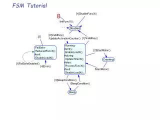
Traffic Light Controller Revisit • A simplified traffic light controller • Traffic sensors (sensing human traffic): TA, TB • Each sensor becomes TRUE if students are present • Each sensor becomes FALSE if students are NOT present (i.e., the street is empty) • Lights: LA, LB • Each light receives digital inputs specifying whether it should be green, yellow, or red
Moore FSM in Verilog // next state logic always @ (*) begin case (currstate) S0: if (~TA) nextstate = S1; else nextstate = S0; S1: nextstate = S2; S2: if (~TB) nextstate = S3; else nextstate = S2; S3: nextstate = S0; default: nextstate = S0; endcase end // output logic always @ (*) begin if (currstate == S0) begin LA = green; LB = red; end else if (currstate == S1) begin LA = yellow; LB = red; end else if (currstate == S2) begin LA = red; LB = green; end else begin LA = red; LB = yellow; end end endmodule `timescale 1ns/1ps module moore_traffic_light (input clk, reset, TA, TB, output reg [1:0] LA, LB); reg [1:0] currstate, nextstate; parameter S0 = 2'b00; parameter S1 = 2'b01; parameter S2 = 2'b10; parameter S3 = 2'b11; parameter green = 2'b00; parameter yellow = 2'b01; parameter red = 2'b10; // state register always @ (posedgeclk, posedge reset) begin if (reset) currstate <= S0; else currstate <= nextstate; end
Simulation with ModelSim • Useful tips in using ModelSim • To display state information as described in Verilog code • Format: radix define name { …. } • Example: radix define mystate {2'b00 "S0" , 2'b01 "S1" , 2'b10 "S2" , 2'b11 "S3" , -default binary} radix define mylight {2'b00 "green" , 2'b01 "yellow" , 2'b10 "red" , -default binary} • Save the display information for the use in the future • File->Save Format, Then click on “OK” • By default, it will save the waveform format to “wave.do”
Snail FSM Revisit • There is a snail • The snail crawls down a paper tape with 1’s and 0’s on it • The snail smiles whenever the last four digits it has crawled over are 1101 1/0 Moore FSM: arcs indicate input 1 0/0 reset 1 1 0 1 S1 0 S0 0 S2 0 S3 0 S4 1 0 0 1 0 0 Mealy FSM: arcs indicate input/output 1/1 reset 1/0 0/0 S1 S0 S2 S3 0/0 1/0 0/0
Moore FSM in Verilog // next state logic always @(*) begin case (currstate) S0: if (bnum) #delay nextstate = S1; else #delay nextstate = S0; S1: if (bnum) #delay nextstate = S2; else #delay nextstate = S0; S2: if (bnum) #delay nextstate = S2; else #delay nextstate = S3; S3: if (bnum) #delay nextstate = S4; else #delay nextstate = S0; S4: if (bnum) #delay nextstate = S2; else #delay nextstate = S0; default: #delay nextstate = S0; endcase end // output logic always @(*) begin if (currstate == S4) smile = 1'b1; else smile = 1'b0; end endmodule Moore FSM: arcs indicate input 1 reset 1 1 0 1 S1 0 S0 0 S2 0 S3 0 S4 1 0 0 1 0 0 `timescale 1ns/1ps module moore_snail(input clk, reset, bnum, output reg smile); reg [2:0] currstate, nextstate; parameter S0 = 3'b000; parameter S1 = 3'b001; parameter S2 = 3'b010; parameter S3 = 3'b011; parameter S4 = 3'b100; parameter delay = 1; // state register always @(posedge reset, posedgeclk) begin if (reset) #delay currstate <= S0; else #delay currstate <= nextstate; end
Mealy FSM in Verilog // next state logic always @(*) begin case (currstate) S0: begin if (bnum) #delay nextstate = S1; else #delay nextstate = S0; end S1: begin if (bnum) #delay nextstate = S2; else #delay nextstate = S0; end S2: begin if (bnum) #delay nextstate = S2; else #delay nextstate = S3; end S3: begin if (bnum) #delay nextstate = S1; else #delay nextstate = S0; end default: #delay nextstate = S0; endcase end // output logic always @(*) begin case (currstate) S3: begin if (bnum) #delay smile = 1'b1; else #delay smile = 1'b0; end default: #delay smile = 1'b0; endcase end endmodule Mealy FSM: arcs indicate input/output 1/0 0/0 `timescale 1ns/1ps module mealy_snail(input clk, reset, bnum, output reg smile); reg [1:0] currstate, nextstate; parameter S0 = 2'b00; parameter S1 = 2'b01; parameter S2 = 2'b10; parameter S3 = 2'b11; parameter delay = 1; // state register always @(posedge reset, posedgeclk) begin if (reset) #delay currstate <= S0; else #delay currstate <= nextstate; end 1/1 reset 1/0 0/0 S1 S0 S2 S3 0/0 1/0 0/0
Simulation with ModelSim • Use radices below for display purpose • radix define moore_state {3'b000 "S0" , 3'b001 "S1" , 3'b010 "S2" , 3'b011 "S3" , 3'b100 "S4" , -default binary} • radix define mealy_state {2'b00 "S0" , 2'b01 "S1" , 2'b10 "S2" , 2'b11 "S3" , -default binary}
HDL Summary • HDLs are extremely important languages for modern digital designers • You are able to design digital systems with HDL much faster than drawing schematics • Debug cycle is also often much faster because modifications require code changes instead of tedious schematic redrawing • However, the debug cycle can be much longer with HDLs if you don’t have a good idea of the hardware your code implies
HDL Summary • The most important thing to remember when writing HDL code is that you are describing real hardware! (not writing a software program) • The most common beginner’s mistake is to write HDL code without thinking about the hardware you intend to produce • If you don’t know what hardware your code is implying, you mostly likely don’t get what you want • When designing with HDL, sketch a block diagram of your system • Identify which portions are combinational logic, sequential logic, FSMs and so on, so forth • Write HDL code for each portion and then merge together