Download
1 / 23
240 likes | 539 Views
Laser Power Meter Calibrations at NIST. Matthew.Spidell@ NIST .GOV. LIGO Gold Standard traceability to the SI Details of the NIST Standard Calorimeter Verification of the NIST standard LIGO Gold Standard test conditions Incident optical power inequivalence contributions.

E N D
Laser Power Meter Calibrations at NIST Matthew.Spidell@NIST.GOV
LIGO Gold Standard traceability to the SI • Details of the NIST Standard Calorimeter • Verification of the NIST standard • LIGO Gold Standard test conditions • Incident optical power inequivalence contributions
Representation of the optical Watt through electrical substitution V Base/Derived Unit C-Calorimeter Primary Standard Defining Constants s Ω h Δν e
Calorimeter Design Insulating shell Heater windings Isothermal vacuum shell Thermal dampening shell Electrical-Substitution heater windings DC Amplifier Carbon-Black absorbing cavity 1° Wedge Window Multi-Junction thermopile/Weak thermal link
Systematic Uncertainty Details • Standard meter ratio (0.29 %) • Uncertainty attributable to pointing instability integrated with last external aperture and /or standard entrance aperture • Inequivalence (0.087 %) • Difference in temperature response between optically delivered power and electrically delivered power (during calibration of the standard) • Window Transmission (0.064%) • Composite polarization and spectral-absorptivity uncertainty • Electronics (0.058 %) • Composite of the pre-amplifier and A-D converter uncertainty contributions
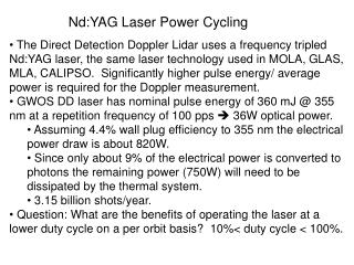
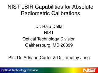
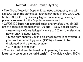
Optical inter-comparisons • Laser Optimized Cryogenic Radiometer • 1 mW • 1 μm • U (k=2) 0.86%
Optical inter-comparisons • K-Series Calorimeter • 2 W • 1 μm • (C.F.= 0.9981) • U (k=2) 1.5%
Kg inter-comparison (via Radiation Pressure Power Meter & K-series calorimeter) • Kg via RPPM & K-Series Calorimeter • (C.F.= 0.9941) • U (k=2) 1.7%
LIGO ‘Gold Standard’ Calibration Conditions • 1047nm Diode Pumped Solid State Source • 1/e2 diameter of approximately 4 mm • 24 Hour+ thermal equilibrium • 20 ± 1 °C • 20 ± 5 % RH
Measurement Procedures • Order of Operations: • Calorimeter vs monitor • Gold Standard vs monitor • Calorimeter vs monitor • Each step consists of 4+ measurements to meet minimum degrees of freedom for a 96% confidence interval Calorimeter Shutter Calorimeter Beamsplitter Laser DUT Data Acquisition and Control
Detailed Calibration Geometry Attenuator Entrance Iris Shutter M1 Standard 2 Standard 1 GS M2 Enclosure Enclosure Beamsplitter
Inequivalence contributors to Standard and Device Under Test incident power
Incident optical power inequivalence contributions • Setup geometry • Intermediate optics (scatter, diffraction, alignment, etc…) • Long paths between last optical element and standards preferred • renders apertures effective against scatter • Minimum 30 cm separation between integrating sphere and any normal surface (more on this latter) • Unintended etalons • Avoid planar beamsplitters (to monitor) • Avoid attenuators after beamsplitter • example: • Assume planar surfaces • R=0.5%
Incident optical power inequivalence contributions (cont.) • Laser induced heating of optics • Absorbing ND filters and invar film attenuators can see laser induced heating and resulting transmission variation • Continually-variable attenuators after the beamsplitter (to monitor) yield splitting ratio variation due to pointing instability • Atmospheric absorption • Typically water lines in Short Wave IR • Negligible at 1047nm, 20 cm gas cell • Source instability • Active power stabilization or Concurrent measurement of a monitor and Standard/Device under test preferred
Test Setup Aperture stop typically located before standard and device under test to ensure scattered light does not yield inequivalence Aperture diameter must exceed main beam diameter to bar against introducing edge diffraction
Test Setup • Reflectance of PTFE >98% at 1047 nm • Integrating spheres can have a diffuse exitance of approximately 50% • Worst case conditions yielded a 2% increase in detected signal • Aperture stops must be located >30 cm from the detector entrance port (empirically determined) Sphere Shell Diffuse reflectance wall material (PTFE) Detector at top of sphere 50% Exitance