Download
1 / 20
210 likes | 311 Views
Chapter 2. Navier-Stokes Modeling for HAWT by CFX 5.7. Rotor Geometry. FIL-1000. 1. Diameter : 54.5 m. 2. Rated Power : 1MW (Design wind speed – 10 m/s). 3. TSR : 7.5 (Design point). 4. Rotating Speed : 26.28 rpm. 5. Power Control Type : Stall regulated.

E N D
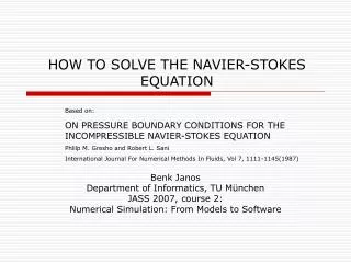
Chapter 2 Navier-Stokes Modeling for HAWT by CFX 5.7
Rotor Geometry FIL-1000 1. Diameter : 54.5 m 2. Rated Power : 1MW (Design wind speed – 10 m/s) 3. TSR : 7.5 (Design point) 4. Rotating Speed : 26.28 rpm 5. Power Control Type : Stall regulated 6. Airfoil Sections : NACA 63415, NACA 63418, DU-Series, FFA Series (From Tip to Hub)
Details of Specification ROOT TIP
Computational Mesh • Mesh Generation : ICEM-CFD 5.0 • Mesh Type : Unstructured Hexa • 480,000 nodes
Computational Mesh • Chord length : 175 nodes • Radial direction : 40 nodes • O-GRID
Computational Mesh • Chord length : 175 nodes • Hybrid-Mesh : Casing (Tetra-Prism) • 220,000 nodes
Turbulence Modeling # K-W SST Model with High Resolution • Accounts for the transport of the turbulence shear stress and gives • very highly accurate predictions of the onset and the amount of • flow separation under adverse pressure gradients • Improve the accuracy for the predictions of the flow separation from • a smooth surface : Important phenomenon in many industrial fields, • particularly for airplane industries • The most prominent two equation model Ref.: Menter, F.R.., “Two equation eddy-viscosty turbulence models for engineering applications” AIAA Journal, 32(8), 1994
Boundary Conditions • Inflow (Normal velocity) • Rotating Frame + Stationary Frame • Periodic surfaces(GGI) • Frame change model : Frozen rotor Interface with rotor and casing • Outflow (Static Pressure)
Results TSR : 3 TSR : 7.5 TSR : 10 Surface Pressure Distribution on the Suction Side
Results TSR : 3 TSR : 7.5 TSR : 10 Surface Streamline on the Suction Side
Results TSR : 3 TSR : 7.5 TSR : 10 Sliced Streamline – 5m from Root
Results TSR : 3 TSR : 7.5 TSR : 10 Sliced Streamline – 10m from Root
Results TSR : 3 TSR : 7.5 TSR : 10 Sliced Streamline – 15m from Root
Results TSR : 3 TSR : 7.5 TSR : 10 Sliced Streamline – 20m from Root
Future Works 수행완료 진행 예정