Download
1 / 27
280 likes | 414 Views
Windows Media Video 9. Tarun Bhatia tarun79_us@yahoo.com Multimedia Processing Lab University Of Texas at Arlington 11/05/04. Introduction 1. Introduction 2. Introduction 3.

E N D
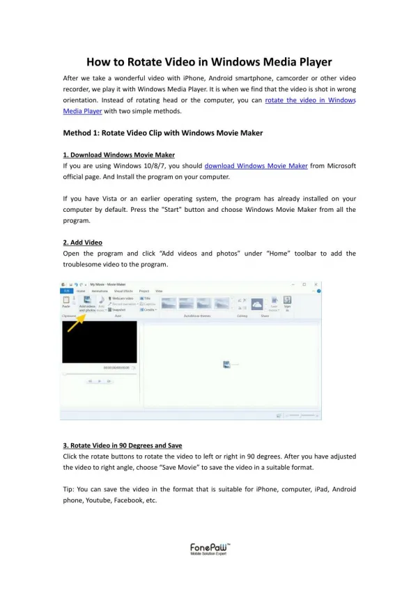
Windows Media Video 9 Tarun Bhatia tarun79_us@yahoo.com Multimedia Processing Lab University Of Texas at Arlington 11/05/04
Introduction 3 • Latest video codec which gives state-of-art video quality from very low bit rates (160x120 at 10 Kbps for modem) to very high bit rates (1920x1080 for HDTV) • 8-bit , 4:2:0 format • Uses block based transform and motion compensation with quantization and entropy coding.
8x8 blocks can be encoded using 1_8x8 2_8x4 2_4x8 4_4x4 Frame / Macroblock/Block signaling Block level for coarse and fine level specification Frame level for overhead reduction Only 8x8 used for I frames Block Transforms(Integer DCT)
WMV 9 H.264 HP 8x8 Integer DCT Matrices
Key features of the Transforms • The norms of vectors of the ratio 288:289:299 • The variation in the norm accounted for in the encoder itself • At the decoder inverse transform(rows) -> rounding-> inverse transform (columns) ->rounding (to operate in the 16 bit range)
Quantization • Same rule applied to all block sizes • Both types with (bit savings at low bit rates) and without dead zone ( available • Type used signaled at the frame level to the decoder • At the encoder side automatic switch from uniform quantization to dead zone quantization as Q – parameter increases • Other factors like noise and rate control can be used to control this switch
Loop Filtering • Done to remove blocky artifacts and thus quality of current frame for future prediction • Operates on pixels on the border of blocks • The process involves a discontinuity measurement • Checks are computationally expensive so done only for one set of pixel per boundary
Motion Estimation and Compensation • Max resolution of ¼ pixel (i.e. ¼, ½, ¾) allowed • 16x 16 motion vectors used by default but 8x8 allowed • Bicubic filter with 4 taps/ Bilinear filters with 2 taps to generate subpixel precision. • 4 combined modes 1.Mixed block size (16x16 and 8x8), ¼ p ,bicubic 2.16x16, ¼ p, bicubic 3.16x16, ½ p, bicubic 4.16x16, ½ p, bilinear • Bilinear filters for chroma components
Advanced entropy coding • Simple VLC codes • Multiple code tables for encoding each particular alphabet out • A possible set of code tables is chosen (based on frame level quantization parameter) and signaled in the bitstream • Additional information e.g. motion vectors resolution coded using bitplane coding
Interlaced coding • Supports field and frame coding
Advanced B frame coding • B frames:- employ bi-directional prediction • Fractional position definition with respect to the reference frames for better scaling of motion vectors • Intra coded B frames for scene changes • Allow inter field reference
Overlap smoothing • The deblocking filter smoothens out the block as well as true edges and it may be disabled in less complex profiles • A lapped transform (input spans to pixels from other blocks as well) is used at the edges • Used in spatial domain as pre and post processing • Used only at low bit rates where blocking artifacts are higher • Signaled at macroblock level so can be turned off in smooth regions
Low rate tools (<100 Kbps) • Code frames at multiple resolutions (both in X and Y direction) • A frame can be downscaled at the encoder and then upscaled at the decoder for LBR transmission • The downscaling factor needs to remain same from the start of 1 I frame to the start of next I frame. • The frame must be upscaled prior to display (upscaling out of scope of the standard).
Fading compensation • Large amount of bits required for scenes having effects like fade-to-black ,fade-from-black • Not possible to predict motion using normally used techniques. • Effective fading detection (original refrence image- current video image>threshold=fading) • If detected then encoder computes fading parameters which specify a pixel-wise first order linear transform for the reference image. • Also signaled to the decoder
References • Windows Media Video 9: overview and applications Sridhar Srinivasan, Pohsiang (John) Hsu, TomHolcom b, Kunal Mukerjee, Shankar L. Regunathan, Bruce Lin, Jie Liang, Ming-Chieh Lee, Jordi Ribas-Corbera Windows Digital Media Division, Microsoft Corporation, Redmond, WA 98052, USA available online at www.sciencedirect.com
AVS China’s next generation video coding standard
Introduction • Streamlined video coder dedicated to coding HDTV content (1920x1080 in 4:2:0 and 4:2:2) • 4 levels are defined Level 4.0 : Standard Definition 4:2:0 Level 4.2 : Standard Definition 4:2:2 Level 6.0 : HD 4:2:0 Level 6.2 : HD 4:2:2 (HD: High Definition) • Designed to provide near optimum performance and considerable reduction in complexity (low cost implementation) • Applications include broadcast TV,HD-DVD and broadband video networking
Data Formats • Progressive scan results in significantly less coding complexity • Interlaced scan
Structure Have start codes
Structure Slice
Structure 4:2:0 4:2:2
Buffers • The rate buffer at the encoder side helps in converting variable data rate produced by encoder to fixed data rate by controlling quantization using feedback • The rate buffer at the decoder side gets the fixed rate data and stores it and then passes on to the decoder at a rate demanded by decoding of each macroblock and frame.