Download
1 / 4
40 likes | 57 Views
High rate of heat flow is the demand of number of engineering applications, heat exchangers used in process industries, economizers used to heat water to boiler or activities like cooling of IC engines. Also, the removal of heat from integral circuit or exchange of heat between two fluids as in nuclear power plants many researchers contributed in enhancement of heat transfer through various approaches. Increase in heat transfer rate and to derive is being done by using different techniques or by performing experiments as well previous literature mentioned the theory regarding heat transfer in such a way that it will increased by increasing area and heat transfer coefficient. In case of natural convection there is only scope for increasing heat transfer area, there extended surfaces i.e. fins are better option to it. Other advantage is increasing turbulence with pitch therefore it enhances heat transfer. Study of heat transfer is possible through numerical experimental analysis. In case of numerical analysis, the results give's heat flow pattern and but less accurate. Whereas experimental analysis gives accurate results but require set up, time and valid conditions. Rohit | Kuldeep "Effect of Different Fin Geometries on Heat Transfer Coefficient" Published in International Journal of Trend in Scientific Research and Development (ijtsrd), ISSN: 2456-6470, Volume-4 | Issue-4 , June 2020, URL: https://www.ijtsrd.com/papers/ijtsrd31613.pdf Paper Url :https://www.ijtsrd.com/engineering/mechanical-engineering/31613/effect-of-different-fin-geometries-on-heat-transfer-coefficient/rohit<br>

E N D
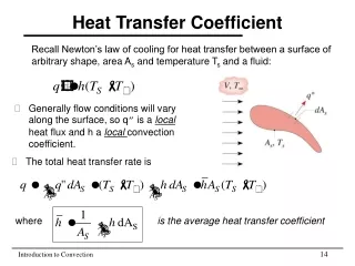
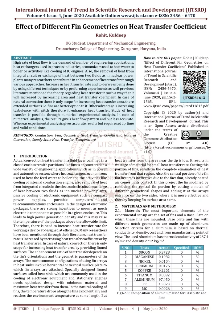
International Journal of Trend in Scientific Research and Development (IJTSRD) Volume 4 Issue 4, June 2020 Available Online: www.ijtsrd.com e-ISSN: 2456 – 6470 Effect of Different Fin Geometries on Heat Transfer Coefficient Rohit, Kuldeep UG Student, Department of Mechanical Engineering, Dronacharya College of Engineering, Gurugram, Haryana, India ABSTRACT High rate of heat flow is the demand of number of engineering applications, heat exchangers used in process industries, economizers used to heat water to boiler or activities like cooling of IC engines. Also, the removal of heat from integral circuit or exchange of heat between two fluids as in nuclear power plants many researchers contributed in enhancement of heat transfer through various approaches. Increase in heat transfer rate and to derive is being done by using different techniques or by performing experiments as well previous literature mentioned the theory regarding heat transfer in such a way that it will increased by increasing area and heat transfer coefficient. In case of natural convection there is only scope for increasing heat transfer area, there extended surfaces i.e. fins are better option to it. Other advantage is increasing turbulence with pitch therefore it enhances heat transfer. Study of heat transfer is possible through numerical experimental analysis. In case of numerical analysis, the results give’s heat flow pattern and but less accurate. Whereas experimental analysis gives accurate results but require set up, time and valid conditions. KEYWORDS: Conduction, Fins, Geometry, Heat Transfer Co-efficient, Natural Convection, Steady State Heat Transfer, Temperature How to cite this paper: Rohit | Kuldeep "Effect of Different Fin Geometries on Heat Transfer Coefficient" Published in International Journal of Trend in Scientific Research and Development (ijtsrd), ISSN: 2456-6470, Volume-4 | Issue-4, June 2020, pp.1562- 1565, URL: www.ijtsrd.com/papers/ijtsrd31613.pdf Copyright © 2020 by author(s) and International Journal of Trend in Scientific Research and Development Journal. This is an Open Access article distributed under the terms of the Creative Commons Attribution License (CC (http://creativecommons.org/licenses/by /4.0) IJTSRD31613 BY 4.0) 1.INTRODUCTION Actual convection heat transfer in a fluid layer confined in a closed enclosure with partitions like fins is encountered in a wide variety of engineering applications. Such as in power and automotive sectors where heat exchangers, economizers used to heat the feed water to boiler and the activities like cooling of internal combustion engine, also removal of heat from integrated circuits in the electronic circuits or exchange of heat between two fluids as inn nuclear power plants, passive cooling of electronic equipment such as compact power supplies, portable telecommunications enclosures. In the design of electronic packages, there are strong incentives to mount as much electronic components as possible in a given enclosure. This leads to high power generation density and this may raise the temperature of the packages above the allowable limit. Therefore, there is need to increase heat transfer rate for working a device at designed at efficiency. Many researchers have been mentioned through their literature, heat transfer rate is increased by increasing heat transfer coefficient or by heat transfer area. In case of natural convection there is only scope for increasing heat transfer area by providing finned surfaces. The enhancement ratio of heat transfer depends on the fin’s orientations and the geometric parameters of fin arrays. The most common configurations of using fin arrays in heat sinks involve horizontal or vertical surface plate to which fin arrays are attached. Specially designed finned surfaces called heat sink, which are commonly used in the cooling of electronic equipment and stationary engines needs optimized design with minimum material and maximum heat transfer from them. In the natural cooling of fins, the temperature drops along the fins exponentially and reaches the environment temperature at some length. But heat transfer from the area near the tip is low. It results in wastage of material for small heat transfer rate. Cutting this portion of fins, results in the complete elimination of heat transfer from that region. Also, the central portion of the fin flat becomes ineffective due to the fact that, already heated air comes in its contact. In this project the fin modified by removing the central fin portion by cutting a notch of different geometrical shapes and adding it at the arrays entrance on the two sides, where it is more effective and thereby keeping fin surface area same. 2.MATERIALS AND METHODOLGY 2.1. Materials The most important elements of the experimental set-up are the set of fins and a Base Plate on which these fins are mounted. Base plate and fins with different notch geometries are made up of aluminum. Selection criteria for a aluminum is based on thermal conductivity, density, cost and from manufacturing point of view. The used Aluminium has thermal conductivity of 237.4 w/mk and density 2712 kg/m3. S.NO. Tests Actual Specified UOM 1. SUCON 0.3728 2. MAGANESE 0.1982 3. NICKEL 0.0104 4. CROMIUM 0.0176 5. COPPER 0.2201 6. TITANUM 0.0092 7. ALUMINIUM 97.450 8. FE 1.3023 9. MG 0.0926 Fig.No.1: Composition of Aluminium used for Baseplate and Fins computers and 0 0 0 0 0 0 0 0 0 % % % % % % % % % @ IJTSRD | Unique Paper ID – IJTSRD31613 | Volume – 4 | Issue – 4 | May-June 2020 Page 1562
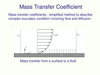
International Journal of Trend in Scientific Research and Development (IJTSRD) @ www.ijtsrd.com eISSN: 2456-6470 required for this purpose are of thickness 2mm which are available in that thickness. All the sets of fins and the base plate are cut and machined in the workshop. Fins with rectangular notch are cut very easily with the hacksaw as the machining of aluminum is very easy. The fins with circular notches are cut with the help of milling machine. Fins with triangular and trapezoidal notches are also cut with the help of hacksaw manually. One set of fins include five number of fin flats. There are five such sets of fins, for the fins without notch, fins with circular notch, fins with rectangular notch, fins with triangular notch, and fins with trapezoidal notch. The dimensions the notches selected as to maintain a surface area in and the depth of notch constant for all notched fins. These three fin flats are mounted on one base. Thus a total number of fin flats fabricated are 18. Only a single base plate is fabricated with notches and the same base plate is used for all the sets of fins. The dimensions of base plate are [200x200] mm the three fins are placed on the base plate in the slots made on the base plate at equal intervals. The distance between the slots thus obtained is 20 mm. Base plates and the set of three fins were assembled. 2.3 Method The Apparatus consisted of Base frame to inscribe various equipments such as Dimmerstat to regulate the voltage supply. Multi-point temperature indicator with digital display in terms of degree Celsius. J-type thermocouple were used to measure the temperature at tip of the fins. A heater of 600 Watt capacity was used to heat the Aluminium base plate to a required temperature. Firstly, the Apparatus was assembled and calibrated to room temperature. The fins of required geometries were fixed on the base plate and the base plate was heated to temperature of 100°C and 120°C for two different set of readings for each fin geometry. There were total of five different geometries that were heated and tested. The base plate and fins attached to it was placed within a box made out of Wood and Asbestos to attain Steady State Heat Transfer. The Baseplate along with the fins was then heated to 100°C for the first set of readings. After the readings were noted down, the Baseplate along with the fins was cooled through natural Convection. The base plate along with the fins was again heated to 120°C for the next set of readings. A correspondig reading was taken for each fin with respect to the base plate temperature at five different locations and the mean was taken. The corresponding readings, for each fin geometry are represented in the following tables Fig.No.2 Aluminium Base Plate Fig.No.3 Fins with different Geometry Fig.No.4 Apparatus of the Experiment Fabrication Sheets of Aluminum are purchased directly from the shops available in the market. The sheets 2.2 Table 1 Fin temperature Readings Base plate temperature (Tb) 101.45°C 120.8°C 100°C 120.3°C 99.85°C 120.3°C 100.1°C 120°C 100.05°C 119.95°C 99.85°C 119.85°C Mean fin temperature (Tf) 92.32°C 108.34°C 96.36°C 116.2°C 93.32°C 11.88°C 91.81°C 108.8°C 92.06°C 109.1°C 91.16°C 110.68°C Chamber temperature (Tchamber) 51.2°C 58.8°C 52.7°C 62.9°C 52.8°C 63.6°C 54.1°C 66.7°C 52.9°C 60.8°C 52.2°C 59.7°C S. NO. Fin Geometry 1 Without Notch 2 Circular Notch 3 Triangular Notch 4 Square Notch 5 Rectangular Notch 6 Comb Profile @ IJTSRD | Unique Paper ID – IJTSRD31613 | Volume – 4 | Issue – 4 | May-June 2020 Page 1563
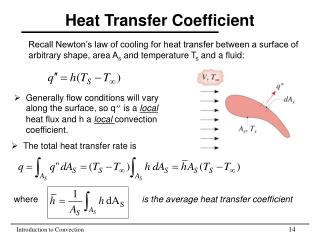
International Journal of Trend in Scientific Research and Development (IJTSRD) @ www.ijtsrd.com eISSN: 2456-6470 2.3.1. Various Parameters required to calculate Heat Transfer Coefficient Temperature of the whole body T(body)=Tb+Tf /2 ,°C 2.3.1.2.Temperature of temperature ∆ T= Tbody−Tchamber ,°C 2.3.1.3.Mean film temperature Tmf=Tbody+Tchamber 2 ,°C 2.3.1.4.Coefficient of volume expansion β=1/ Tmf 2.3.1.5.Grashof Number 3.RESULTS AND DISCUSSION 3.1. Graphical Representation of Results Gr = gβ∆TL3c/ Y2 L c= characteristic length of geometry, m ?? = kinematic viscosity of fluid,m2/s g= Acceleration dure to gravity, m/s2 ∆T= Temperature of the Body and surrounding temperature β = Grashof’s Number 2.3.1.6.Rayleigh number Ra=GrPr Pr=Prandtl number 2.3.1.7.Nusselt number If 104<GrPr<109 then, Nu =0.59(GrPr)(1/4) If 109<GrPr<1012 then, Nu =0.59(GrPr)(1/3) 2.3.1.8 Heat Transfer Coefficient H= Nuk/Lc, W/m2k 2.3.1.1. body and surrounding 9.8 9.6 9.4 9.2 9 8.8 8.6 8.4 8.2 8 h(w/m2k) notch profile ℃ base temperature for various notch profiles Fig.No.5 Comparison of Heat Transfer Coefficient at 100 ℃ ℃ ℃ 10.5 10 9.5 9 8.5 8 h(w/m2k) notch profile ℃ ℃ ℃ base temperature for various notch profiles Fig.No.6 Comparison of Heat Transfer Coefficient at 120 ℃ @ IJTSRD | Unique Paper ID – IJTSRD31613 | Volume – 4 | Issue – 4 | May-June 2020 Page 1564
International Journal of Trend in Scientific Research and Development (IJTSRD) @ www.ijtsrd.com eISSN: 2456-6470 Discussion It is clearly visible from the above results table that the geometry of the fin can have a considerable amount of difference in the Heat Transfer Coefficient. We can say that as the fin geometry changes, the Heat Transfer Coefficient also changes. From various geometries which were put under the test, the Comb shaped notch profile in the fin tends to have maximum Heat Transfer Coefficient among all the other geometrics of the fin. 4.CONCLUSIONS It is proved that the heat transfer coefficient is highest for the set of fins with comb profile (9.6290 W/m2K) at base temperature 100℃ and (10.2232W/m2K) at base temperature 120℃. This has been shown by the experimental analysis. From the Experimental analysis it has been observed that temperature distribution for the notched fins is more uniform than the fins without notch. It is observed that the heat transfer coefficient varies with notch geometry. As area removed from the fin at the air entry ends of the fin, it provides chance to get greater amount of fresh air in contact. From, economical point of view, along with increasing Heat Transfer Coefficient. it saves the fin material and indirectly cost of the production. Along, with Experimental analysis, numerical simulation may be defined through CFD tool for predicting heat transfer phenomena and temperature gradient along the finned area. Study can be extended by analysis to be carried out with forced convection and results can be predicted for different Reynolds numbers. Further analysis can be carried out on the basis of surface roughness and orientation of fins. 5.REFERENCES [1]S. A. Nada, ‘Natural convection heat transfer in horizontal and vertical closed narrow enclosures with heated rectangular finned base plate’, J. Heat transfer Vol. 116, pp 75-81. [2]H. G. Yalcinet. Al, ‘Study of effect of clearance parameters on the steady-state heat transfer’, ASEM journal of heat transfer, Vol. 103, pp.616.623. [3]S. S. Sane1, N. K. Sane2, G. V. Parishwad3, ‘Computational analysis of horizontal rectangular notched fins arrays dissipating heat by natural convection.’ [4]P. K. Nag, 2006, ‘Heat and mass transfer’, 2nd Edition, Tata McGraw Hill Co. Page No.: 86-108 and 425-449. [5]J. P. Holman, 2004, ‘Heat transfer- A particle approach.’ SI units 2nd Edition, Tata McGraw Hill Co., Page No.:156-168, 333352, and 459-500. [6]El Hassan Ridouane and Antonio Campo, ‘Heat transfer and pressure drop characteristics of laminar air flows moving in parallel plate channel with transverse hemi- cylindrical cavities’, International journal of heat and mass transfer, Vol. 50, September 2007. [7]W. W. Lin and D. J. Lee, ‘second law analysis on a flat plate fin array under cross-flow’, International communications in heat and mass transfer, Vol. 27, issue 2, February 2000. [8]Gutavo Ledezma and Adrian Bejan, ‘heat sinks with sloped plate fins in natural and forced convection’, International Journal of heat and mass transfer, vol. 39, issue 9, June 1996. @ IJTSRD | Unique Paper ID – IJTSRD31613 | Volume – 4 | Issue – 4 | May-June 2020 Page 1565