Download

1 / 5
50 likes | 54 Views
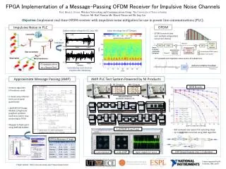
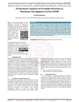
Power Line Communication PLC becomes the preferred technique for providing broadband to homes and offices with the advantage of eliminating the need for new wiring infrastructure and reducing the cost. An effect of an impulsive noise is identified as one of the major impairment in PLC. Orthogonal Frequency Division Multiplexing OFDM is one of the modulation techniques for PLC by most researchers and is used in this research. The performance of OFDM is analysed by adding Middleton Class A noise and applying it to the channel in an attempt to corrupt the signal. The results will show that the different modulation orders of Phase Shift Keying PSK are applied to test the input image which may be any size of a gray scale image or a colour image by comparing the values of Bit Error Rate BER , the average phase error and the percentage of pixel errors in the operation of OFDM system. In doing so, GUI from MATLAB software is used to simulate the operation of virtual transmitter and receiver. Phyu Mar Kyu | Chaw Myat Nwe "Performance Analysis of OFDM System for Middleton Class A Noise" Published in International Journal of Trend in Scientific Research and Development (ijtsrd), ISSN: 2456-6470, Volume-3 | Issue-4 , June 2019, URL: https://www.ijtsrd.com/papers/ijtsrd25148.pdf Paper URL: https://www.ijtsrd.com/engineering/electronics-and-communication-engineering/25148/performance-analysis-of-ofdm-system-for-middleton-class-a-noise/phyu-mar-kyu<br>

E N D
International Journal of Trend in Scientific Research and Development (IJTSRD) Volume: 3 | Issue: 4 | May-Jun 2019 Available Online: www.ijtsrd.com e-ISSN: 2456 - 6470 Performance Analysis of OFDM System for Middleton Class A Noise Phyu Mar Kyu, Chaw Myat Nwe Department of Electronic Engineering, Mandalay Technological University, Mandalay, Myanmar How to cite this paper: Phyu Mar Kyu | Chaw Myat Nwe "Performance Analysis of OFDM System for Middleton Class a Noise" Published in International Journal of Trend in Scientific Research and Development (ijtsrd), ISSN: 2456- 6470, Volume-3 | Issue-4, June 2019, pp.1591-1595, URL: https://www.ijtsrd.c om/papers/ijtsrd25 148.pdf Copyright © 2019 by author(s) and International Journal of Trend in Scientific Research and Development Journal. This is an Open Access article distributed under the terms of the Creative Commons Attribution License (CC BY 4.0) (http://creativecommons.org/licenses/ by/4.0) There are three different network levels are in the PLC. They are high voltage (HV) which has the range of 69-380kV, medium voltage (MV) which is from 2.4kV to 35kV and low voltage (LV) which has the voltages up to 600V [1]. Moreover, there are two transmissions in PLC such as broadband power line communication (BPL) which operates with a carrier frequency range of 2-30 MHz to achieve data rates up to 200 Mbps and narrowband power line communication (NPL) which operates in the frequency bands between 3 kHz and 500 kHz to achieve data rates from 10kbps to 500kbps [2] shown in Fig.1. ABSTRACT Power Line Communication (PLC) becomes the preferred technique for providing broadband to homes and offices with the advantage of eliminating the need for new wiring infrastructure and reducing the cost. An effect of an impulsive noise is identified as one of the major impairment in PLC. Orthogonal Frequency Division Multiplexing (OFDM) is one of the modulation techniques for PLC by most researchers and is used in this research. The performance of OFDM is analysed by adding Middleton Class A noise and applying it to the channel in an attempt to corrupt the signal. The results will show that the different modulation orders of Phase Shift Keying (PSK) are applied to test the input image which may be any size of a gray-scale image or a colour image by comparing the values of Bit Error Rate (BER), the average phase error and the percentage of pixel errors in the operation of OFDM system. In doing so, GUI from MATLAB software is used to simulate the operation of virtual transmitter and receiver. Keywords: Power Line Communication; OFDM; PSK; Middleton Class A noise I. INTRODUCTION The Power Line Communication (PLC) refers to a technology for transmitting data using power lines in the frequency range of 50-60 Hz. It exploits the power line infrastructure to provide high-speed broadband to customers and does not require new wiring installation in the building which is a great cost saving. IJTSRD25148 attenuation which increases with high frequencies and can be severe for long distance communications. Signal reflection is caused by impedance mismatching which increases the multipath fading. The noise is produced by various appliances that are connected or linked to PLC transmission channel. Therefore, it is important to choose a better modulation technique for the PLC system. There are various available modulation techniques such as a multicarrier modulation, single carrier and spread spectrum modulation. A multicarrier modulation technique such as an OFDM is a modulation technique of choice for PLC systems because of having better performance in comparison with a single carrier modulation and its performance in impulsive noise environments [3] shown in Fig.2. Figure1: Configuration of power line networks [2] The multipath affects, attenuations and noises are the most significant factors affecting communications over power lines. Power line cables suffer from frequency dependent Figure 2: Available modulation approaches [3] @ IJTSRD | Unique Paper ID – IJTSRD25148 | Volume – 3 | Issue – 4 | May-Jun 2019 Page: 1591
International Journal of Trend in Scientific Research and Development (IJTSRD) @ www.ijtsrd.com eISSN: 2456-6470 OFDM COMMUNICATION Orthogonal Frequency Division Multiplexing (OFDM) has been referred to as one of the most advantageous technique. OFDM systems have been widely recognised as a bandwidth efficient transmission technique communications. This multicarrier transmission technique has been gaining more and more interest from communications and signal processing communities [4]. OFDM is also considered as one of the most promising modulation methods for power line communications [5]. The aim of this paper is to analyze the performance of OFDM system for power line communication noise, using GUI from MATLAB to simulate the operation of virtual transmitter and receiver. Especially, the overall aim of this paper is to test an OFDM system for a power line communication in order to propose and examine a novel approach in comparing the different modulation orders of PSKsuch as BPSK, QPSK, 16- PSK and 256-PSK and also the application of Middleton Class A noise and applying it to the channel in an attempt to understand and recognize the most suitable technique for the transmission of an image within a communication system. The first step is to design a basic OFDM system by using BPSK and the second is to design a more comprehensive OFDM for the purpose of simulation by using Cyclic Prefix (CP), with the aim of counteracting the effects of delay such as Inter-Symbol Interference (ISI) and Inter-Channel Interference (ICI). An additional comparative performance studies will be conducted by tabling the values of BER, average phase error and the percentage of pixel errors for the different modulation orders of PSK. Moreover, additional analysis will be carried out in order to examine the overall performance of the OFDM system by using Middleton Class A noisewhich is a type of the impulsive noise in power line communications. Finally, the full functioning OFDM system is examined through the transmission of an image. Fig. 3 describes the block diagram of OFDM system with power line communication noise which is designed in this research paper. II. MODEL FOR POWER LINE III. The data transmission over power lines provides many attractive properties. However, PLC systems are at risk of internal or external noise and disturbances like all other communication systems. PLC noises can be classified into three categories as follows [6]: Colored background noise which is caused by summation of numerous noise sources of low power. (Up to 30 MHz) Narrow band noise, mostly amplitude modulated sinusoidal signals caused by ingress of radio broadcasting stations. (1 - 22) MHz Impulsive noise Periodic impulsive noise Periodic impulsive noise asynchronous to the mains frequency, which is mostly caused by switching the power supplies. (50 – 100) Hz Periodic impulsive noise synchronous to the mains frequency, which is mainly caused by switching actions of rectifier diodes found in many electrical appliances. (50 – 200) Hz Asynchronous impulsive noise, which is by switching transients in the power network. Middleton Noise Models Middleton Class A noise has been originally defined in order to compare the bandwidth of noise or keep it less than the bandwidth of the receiving system. Middleton Class B noiseis that the noise pulses are able to produce transients within the receiver as the noise bandwidth is greater than the receiving system bandwidth. Middleton Class C noise is a linear sum of Class A and B. The derivation models concise exposition has been presented by Skomal [7]. This paper offers an insight into the influence of power line communication noise as Middleton Class A noise. A.Middleton Class A Noise Middleton classifies the noise in three general classes of Middleton Class A, B and C according to the bandwidth of the noise emitted by each of the interferers, [8]. This paper considers focusing on the Middleton Class A noise model. Its bandwidth is assumed to be comparable or less than the bandwidth of the disturbed communication system and so transient effects in the analogue receiver stages can be neglected. As this paper is partly concentrated on the influence of impulsive noise on OFDM transmission, the channel model for the additive impulsive noise channel will be kept simple as the following equations; Where, s(t) = The transmitted signal n(t) = Class A distributed random variable r(t) = The received signal Additionally, a Gaussian noise component is added to model that always present thermal receiver noise. The Middleton Class A noise PDF is given by equation (2) which is substituted by equations (3-5) [9]. NOISES IN POWER LINE COMMUNICATION for wireless (1) Figure3: Block diagram of OFDM system with Middleton Class A noise (2) @ IJTSRD | Unique Paper ID – IJTSRD25148 | Volume – 3 | Issue – 4 | May-Jun 2019 Page: 1592
International Journal of Trend in Scientific Research and Development (IJTSRD) @ www.ijtsrd.com eISSN: 2456-6470 (3) Start (4) Original Image Resize image into 256 gray-scale bitmap image (5) Where, m = The number of impulsive noise sources A = Impulsive index ? = The Gaussian to impulsive noise ratio (GIR) = The impulsive noise power = The variance of Gaussian noise components IV. DIGITAL MODULATION TECHNIQUES The nature of OFDM only allows the signals to be modulated in amplitude and phase only [12]. This work focuses on PSK technique only. The performance of this modulation technique in a PLC system is evaluated in terms of bit error probability. Phase-shift keying (PSK) may be a digital modulation theme that conveys information by dynamical, or modulating, the section of a reference signal (the carrier wave). A.Binary Phase Shift Keying (BPSK) A binary phase shift keying (BPSK) signal is outlined by s(t) = A m(t) cos 2πfct, (0 < t < T) Where Ais a constant, m (t) = +1 or -1, fcis the carrier frequency, and Tis the bit duration. The signal has a power P = A2/2, so that . B.M-ary Phase Shift Keying (M-PSK) An M-ary phase-shift keying (M-PSK) signal can be defined by IFFT sizes No Number of carriers <=[(IFFT/2)-2] Yes SNR valuses Choose Modulation Scheme (BPSK, QPSK, 16-PSK,256-PSK) Middleton Class A noise in Channel Receive the embedded image and reconstruct the image Compute BER, pixel error and phase error to justify the quality of image (9) End Figure 4: Flow chart of testing an input image through OFDM system with Middleton Class A noise VI. SIMULATION RESULTS AND ANALYSIS This section concentrates on presenting the simulation response for different simulation results, considering the comparison for different modulation orders of PSK, total number of errors, BER, average phase errors and percentage of pixel errors for the channel which is added by adding Middleton Class A noise. A.Testing an image through BPSK in GUI , (0< t< T) (10) for i = 0, 1, ..., M - 1. Here, A is a constant, fc is the carrier frequency, θ' is the initial phase angle, and T is the symbol duration [13]. V. SOFTWARE IMPLEMENTATION Initially an input image which may be any size of a gray-scale image or a colour image is resized into 256-gray image and compared the received image values of Bit Error Rate (BER), the average phase error and the percentage of pixel errors in the operation of OFDM system by using GUI from MATLAB software. The user input variables include: Input file – an 8-bit gray-scale (256 gray levels); IFFT size – an integer of a power of two; Number of carriers – not greater than [(IFFT size)/2 – 2]; Digital modulation method – BPSK, QPSK, 16-PSK, or 256-PSK. If the number of carriers is greater than [(IFFT size)/2-2], the program will stop definitely. The overall flow chart for this research is shown in Fig.4. Figure 5: Transmission an image through BPSK in OFDM The values of IFFT size, number of carriers and SNR are 1024, 510 and 25 that are used to apply an image in OFDM with BPSK modulation to get these values of total number of @ IJTSRD | Unique Paper ID – IJTSRD25148 | Volume – 3 | Issue – 4 | May-Jun 2019 Page: 1593
International Journal of Trend in Scientific Research and Development (IJTSRD) @ www.ijtsrd.com eISSN: 2456-6470 errors, BER in percentage, average phase errors in degree, pixel errors in percentage and transmitted channels with noises are shown in Fig.5 and 6. C.Testing an image through 16-PSK in GUI Figure 9: Transmission an image through 16-PSK in OFDM Figure 6: Transmitted channel with Middleton Class A noise The values of IFFT size, number of carriers and SNR are 1024, 510 and 25 that are used to apply an image in OFDM with 16-PSK modulation to get these values of total number of errors, BER in percentage, average phase error in degree pixel errors in percentage and transmitted channel with noises are shown in Fig.9 and 10. B.Testing an image through QPSK in GUI Figure 7: Transmission an image through QPSK in OFDM The values of IFFT size, number of carriers and SNR are 1024, 510 and 25 that are used to apply an image in OFDM with QPSK modulation to get these values of total number of errors, BER in percentage, average phase error in degree, pixel errors in percentage and transmitted channel with noises are shown in Fig.7 and 8. Figure 10: Transmitted channel with Middleton Class A noise D.Testing an image through 256-PSK in GUI Figure 8: Transmitted channel with Middleton Class A noise Figure 11: Transmission an image through 256-PSK in OFDM @ IJTSRD | Unique Paper ID – IJTSRD25148 | Volume – 3 | Issue – 4 | May-Jun 2019 Page: 1594
International Journal of Trend in Scientific Research and Development (IJTSRD) @ www.ijtsrd.com eISSN: 2456-6470 The values of IFFT size, number of carriers and SNR are 1024, 510 and 25 that are used to apply an image in OFDM with 256-PSK modulation to get these values of total number of errors, BER in percentage, average phase error in degree, pixel errors in percentage and transmitted channel with noises are shown in Fig. 11 and 12. Figure 12: Transmitted channel with Middleton Class A noise After adding Middleton Class A noise, especially 256-PSK modulated received image has most of the information is still observable even high BER. For example, at 25 dB of SNR, even though the 256-PSK received image has a BER of 83.030303 %, the image is still observable. For gray-scale digital images, if the decoded value of a pixel is off by a small number of gray levels, it’s not easily observed by human eye, but will be counted as a bit error. It’s obvious that the gray level on most of the pixels changed when toggling between the original and received image, but the relatively contents are still somewhat intact. The overall error results of BPSK, QPSK, 16-PSK and 256-PSK in OFDM system are shown in Table.1. BPSK is better than other modulation orders of PSK by analyzing all results. TABLE I. Error calculation results of Ofdm system with Middleton Class A noise Error Calcula-tions BPSK QPSK Total numb-er of errors 0 out of 402600 0 out of 201300 BER (%) 0.000000% 0.000000% Phase errors (deg) 0.012071 (degree) 2.541128 (degree) Pixel errors (%) 0.000000% 0.000000% VII. CONCLUSION In this paper, performance analysis of OFDM system for power line communication was presented. In doing so, GUI from MATLAB software was used to simulate the operation of virtual transmitter and receiver. The performance of the system design was then analyzed by adding Middleton Class A noise and in an attempt to corrupt the signal. The simulation results presented in this project suggest that BPSK is the most preferred modulation technique than other high orders of PSK by comparing their considerable performances. So BPSK modulation is more suitable to design in OFDM system for power line communication. Indeed, applying Middleton Class A noise to the channel has proven very successful and will be accounted as a novel approach for the transmission of an image within OFDM system. ACKNOWLEDGEMENT First and foremost, the author would like to thank her academic supervisor, Dr. Chaw Myat Nwe, Professor at the Department of Electronic Engineering in Mandalay Technological University, and gratefully thanks her for kindness and providing with motivation, thoughtful suggestions, perceptive comments and observant guidelines. The author also would like to express her appreciation to Dr. Sint Soe, Rector and Principle at Mandalay Technological University and Dr. Tin Tin Hla, Professor and Head of the Department of Electronic Engineering at Mandalay Technological University, and then all teachers for their kindness with sharing technical knowledge and supporting. The author specially thanks to her family and her friends for their supports and encouragement. REFERENCES [1]Ali Hosseinpour, “Investigation of Orthogonal Frequency Division Multiplexing Based Power Line Communication Systems”, February 2015. 16-PSK 256-PSK 1969 out of 100650 41785 out of 50325 1.956284% 3.777986 (degree) 3.825137% 83.030303% 1.337460 (degree) 83.030303% [2]Mehdi Korkir, “Power Line Communication Channel Modelling and Performance Evaluation”, 2012 [3]Gotz, M., Rapp, M. & Dostert, K., “Power Line channel Characteristcs and their effect on communication system design”, IEEE Communication magazine, 2004. [4]R. V. Nee, and R. Prasad, “OFDM for wireless multimedia communications”, Artech House Inc., 2000. [5] M. Engels, “Wireless OFDM systems: How to make them work?”, Springer, 2002. [6]A. B. Narasimhamurthy, M. K. Banavar, and C. Tepedelenlio˘glu, “OFDM Systems for Wireless Communications, Morgan & Claypool Inc”, 2010. [7]Middleton, D., “Procedures for Determining the Parameters of the First-order canonical Models of Class A and Class B Electromagnetic Interference”, IEEE Trans.Electromagn.Compat, EMC-21(3), Aug.1979. [8]D. Middleton, “Canonical and Quasi-Canonical Probability Models of Class A Interference”, IEEE Transactions on Electormagnetic Compatibility, Vol. EMC-25, No. 2, May 1983. [9]Jiirgen Haring, Han Vinck, “OFDM Transmission Corrupted by Impulsive Noise”, ISPLC, 2000. [10]Kansal, L., Kansal, A. and Singh, K., “Performance analysis of MIMO-OFDM system using QOSTBC code structure for M-QAM”, Canadian Journal on Signal Processing, 2(2), 4-15, 2011. [11]Ali Kamal Taqi, “Implementation of Digital Modulation Technique and Calculate the Bit Error Rate Performance using Matlab”, IJSER, vol. 7, issue. 8, August 2016 @ IJTSRD | Unique Paper ID – IJTSRD25148 | Volume – 3 | Issue – 4 | May-Jun 2019 Page: 1595