Download
1 / 3
30 likes | 32 Views
In this work multi phase flow and erosion analysis were done via simulations and CFD application for standard diesel and two alternative bio fuels, FAME and DME, inside different nozzle models and with various boundary conditions. Nozzle model consists of narrow channel with sharp type I or rounded type Y inlet section, with or without downstream placed target, so there was a total of four different model geometries. Simulation results showed that cavitations was present in almost all cases and that clear difference between three observed fuels can be seen. Mass flow in channel type I was lower than one in channel type Y. When comparing three observed fuels, it was noticed that DME fuel usually had highest velocity, but lowest mass flow rate. Contrary to DME, FAME fuel showed highest mass flow rate despite lowest velocity. When comparing simulation results and physical properties of observed fuels, it can be concluded that density is a leading term in determining mass flow rate. Also, erosion model predicts more intensive MDPR value near narrow channel exit. Abhishek Sarathe | Yogesh Yadav "CFD Investigation on Nozzle Considering Fuel Properties of Alternative Fuel: A Review" Published in International Journal of Trend in Scientific Research and Development (ijtsrd), ISSN: 2456-6470, Volume-3 | Issue-1 , December 2018, URL: https://www.ijtsrd.com/papers/ijtsrd19090.pdf Paper URL: http://www.ijtsrd.com/engineering/mechanical-engineering/19090/cfd-investigation-on-nozzle-considering-fuel-properties-of-alternative-fuel-a-review/abhishek-sarathe<br>

E N D
International Journal of Trend in International Open Access International Open Access Journal | www.ijtsrd.com International Journal of Trend in Scientific Research and Development (IJTSRD) Research and Development (IJTSRD) www.ijtsrd.com ISSN No: 2456 ISSN No: 2456 - 6470 | Volume - 3 | Issue – 1 | Nov 1 | Nov – Dec 2018 CFD Investigation Fuel Properties Properties of Alternative Fuel: A Review Investigation on Nozzle Considering n Nozzle Considering : A Review Abhishek Sarathe1, Yogesh Yadav2 Abhishek Sarathe 1Research Scholar, Research Scholar, 2Assistant Professor Department of Mechanical Engineering, Millennium Institute of Technology Bhopal, Madhya Pradesh, India Department of Mechanical Engineering, Millennium Institute of Te chnology, ABSTRACT In this work multi phase flow and erosion analysis were done via simulations & CFD application for standard diesel and two alternative bio fuels, FAME and DME, inside different nozzle models and with various boundary conditions. Nozzle model consists of narrow channel with sharp (type I) or rounded (type Y) inlet section, with or without downstream placed target, so there was a total of four different model geometries. Simulation results showed that cavitations was present in almost all cases and that clear difference between three observed fuels can be seen. Mass flow in channel type I was lower than one in channel type Y. When comparing three observed fuels, it was noticed that DME fuel usually had highest velocity, but lowest mass flow rate. Contrary to DME, FAME fuel showed highest mass flow rate despite lowest velocity. When comparing simulation results and physical properties of observed fuels, it can be concluded that density is a leading term in determining mass flow rate. Also, erosion model predicts more intensive MDPR value near narrow channel exit. KEY WORDS: CFD Analysis, Nozzle cavitations, AVL Analysis INTRODUCTION Alternative fuels are lately becoming more and more interesting due to a fact that they don't contribute increasing of carbon in atmosphere in Earth's atmosphere carbon-cycle. In Europe and U.S. fuels gained from rapeseed (RME) and soybean (SOME), together called FAME fuels or biodiesel, are used as an alternative fuel or as a compound in standard diesel/biodiesel mixture. Another biofuel is very interesting, DME, which can be gained from all sorts interesting, DME, which can be gained from all sorts of different sources. In Europe there are currently several active norms that are regulating amount of biodiesel in mineral diesel (EN 590 allow up to 5%), as well as properties of FAME fuels (EN 14241). Diesel fuel injection equipment manufacturers brought common statement in which they support the development of compression ignition alternative fuels. Diversity of physical properties between mentioned fuels causes their different flow characteristics inside fuel nozzles. In this work flow simulations with analyses were performed in different nozzle models, for every inlet/outlet pressure drop and three different fuels. Calculations were done via CFD. Analysis is performed by following criteria: volume fraction distribution due to cavitations, achieved mass flow rate and velocity profile in narrow channel section. Additional figures are presented: pressure, absolute velocity and turbulence kinetic energy distribution. Also, erosion modelling was done. For simulations is used one of the commercially available CFD application, AVL's CFD Workflow Manager with FIRE CFDWM/FIRE). In CFDWM/FIRE one can perform simulations of multiphase flows via module with Erosion modelling included. LITERATURE REVIEW: There are some papers which have be referred on my work. Junmei Shi et al. CFD investigation of fuel properties effect on cavitating flow in generic nozzle geometries Fuel saturation vapour pressure variation up to 0.8 bar has know essential effect on cavitation has know essential effect on cavitation In this work multi phase flow and erosion analysis were done via simulations & CFD application for standard diesel and two alternative bio fuels, FAME and DME, inside different nozzle models and with various boundary conditions. Nozzle model consists rrow channel with sharp (type I) or rounded (type Y) inlet section, with or without downstream placed target, so there was a total of four different Simulation results showed that cavitations was present in almost all cases and that difference between three observed fuels can be seen. Mass flow in channel type I was lower than one in channel type Y. When comparing three observed fuels, it was noticed that DME fuel usually had highest velocity, but lowest mass flow rate. Contrary E, FAME fuel showed highest mass flow rate When comparing simulation results and physical properties of observed fuels, it can be concluded that density is a leading term in determining mass flow rate. Also, erosion model ore intensive MDPR value near narrow of different sources. In Europe there are currently active norms that are regulating amount of biodiesel in mineral diesel (EN 590 allow up to 5%), as well as properties of FAME fuels (EN 14241). Diesel fuel injection equipment manufacturers brought common statement in which they support the compression ignition alternative fuels. Diversity of physical properties between mentioned fuels causes their different flow characteristics inside fuel nozzles. In this work flow simulations with analyses were performed in different nozzle models, very inlet/outlet pressure drop and three different fuels. Calculations were done via CFD. Analysis is performed by following criteria: volume fraction distribution due to cavitations, achieved mass flow rate and velocity profile in narrow channel section. Additional figures are presented: pressure, absolute velocity and turbulence kinetic energy distribution. Also, erosion modelling was done. For simulations is used one of the commercially available CFD application, AVL's CFD Workflow Manager with FIRE CFDWM/FIRE). In CFDWM/FIRE one can perform simulations of multiphase flows via Multiphase module with Erosion modelling included. sol solver (hereafter CFD Analysis, Nozzle cavitations, Alternative fuels are lately becoming more and more interesting due to a fact that they don't contribute increasing of carbon in atmosphere in Earth's cycle. In Europe and U.S. fuels gained from rapeseed (RME) and soybean (SOME), called FAME fuels or biodiesel, are used as an alternative fuel or as a compound in standard diesel/biodiesel mixture. Another biofuel is very e are some papers which have been studied and CFD investigation of fuel properties effect on cavitating flow in generic nozzle geometries Fuel saturation vapour pressure variation @ IJTSRD | Available Online @ www.ijtsrd.com www.ijtsrd.com | Volume – 3 | Issue – 1 | Nov-Dec 2018 Dec 2018 Page: 783
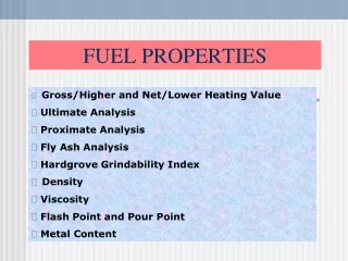
International Journal of Trend in Scientific Research and International Journal of Trend in Scientific Research and Development (IJTSRD) ISSN: 2456 Development (IJTSRD) ISSN: 2456-6470 this is due to the very high pressure gradient caused by the flow acceleration in the nozzle. Takenaka et al. CFD analysis of nozzle cavitations Investigation of cavitation phenomena showed that for nearly all the duration of the injection process the nozzle injector hole is surrounded by cavitation films Berchiche et al For interfacial mass exchange Linear Cavitation Model was used and for interfacial momentum exchange Cavitation Drag Model was used. Both interfacial exchange models imply two additional transport equations: Bubble Number Density and Interfacial Area equation. These equations bring up additional closure coefficients of mathematical model. Semelsberger et al FAME fuel achieves highest mass flow rates in all cases. DME has lowest mass flow rates. Generally, mass flow rates in Channel Y cases are higher than ones in Channel I cases for same boundary conditions. Both interfacial exchange models imply two additional transport equations: Bubble Number Density and Interfacial Area equation. These equations bring up additional closure coefficients of mathematical model. Ornella Chiavola et al On a modified VCO nozzle layout for diesel common rail injectors under actual needle displacement FAME fuel achieves highest mass flow rates in all cases. DME has lowest mass flow rates. Generally, mass flow rates in Channel Y cases are higher than ones in Channel I cases for same boundary conditions. METHOD USED ?In this work quasi-stationary, inner, non compressible, viscous, turbulent and two (generally multiphase) type of flow is assumed, so simulation is set-up assumptions. Two-phase flow implies bubble number density and interfacial area between liquid and gas phase, so additional transport equations for modelling cavitation should be active in order to describe phase change. ? All conservation equations can be written in generic form Turbulence model is a part of a Eddy Viscosity Models (EVM) with two equations EVM assumes direct analogy between molecular and turbulent momentum. Based o assumption. ?Erosion is in Multiphase module modelled within Erosion is in Multiphase module modelled within this is due to the very high pressure gradient caused two model quantities Erosion Incubation Time Mean Depth Penetration Dimensions that are strictly defined: nozzle model thickness, narrow channel, target and coordinate). Length (x coordinate) of inlet and outlet zone is not strictly selected to give developed flow on inlet and outlet zone Calculation stability is also affected with these parameter. ties Erosion Incubation Time Penetration Mean Dimensions that are strictly defined: nozzle model thickness, narrow channel, target and height (y coordinate). Length (x coordinate) of inlet and outlet zone is not strictly defined and should be selected to give developed flow on inlet and outlet Calculation stability is also affected with Depth Rate Rate (MDPR) (MDPR) CFD analysis of nozzle cavitations Investigation of cavitation phenomena showed that for nearly all the duration of the injection process the zzle injector hole is surrounded by cavitation films. For interfacial mass exchange Linear Cavitation Model was used and for interfacial momentum exchange Cavitation Drag Model was used. Both interfacial exchange models imply two transport equations: Bubble Number Density and Interfacial Area equation. These equations bring up additional closure coefficients of ?Because of overall of four different nozzle model types, and computational domains hereafter computational domains as: •Channel I → channel type I without target •Channel Y → channel type Y without target •Target I → channel type I with downstream placed target •Target Y → channel type Y with downstream placed target SELECTIONS AND BOUNDARY COND All domain meshes have same number and type of selections. Boundary conditions must be every phase separately, except pressure which is coupled variable and is defined only for continuous phase. Also, total of phase volume fractions must be equal to one. Since driving force for flow quantities is pressure difference between inlet and ou in order to avoid too long mesh on inlet zone, flow direction on inlet selection is determined. Boundary turbulence parameters were pre CONCLUSIONS CFDWM/FIRE application can give us valuable data regarding multiphase cavitating flow inside nozzles. is shown that mathematical model is valid for its purpose and that nozzle flow for different fuels can be done. when comparing different fuels simulation results, some obvious differences can be observed. Most significant conclusion regarding to comparison between fuels is that in mass flow rate equation, fluid density is more significant term than molecular viscosity. This is concluded based on fact that in almost all cases DME fuel had highest velocity but lowest mass flow rate. If we combine that with fluid properties above conclusion can be derived. REFERENCES 1.Hammond G.P., Kallu S., McManus M.C., Development of biofuels for the UK market, Applied Energy, 2006. , Applied Energy, 2006. Because of overall of four different nozzle model types, and computational domains respectively, hereafter computational domains will be referred channel type I without target channel type Y without target channel type I with downstream AME fuel achieves highest mass flow rates in all cases. DME has lowest mass flow rates. Generally, mass flow rates in Channel Y cases are higher than ones in Channel I cases for same Both interfacial exchange models imply two additional transport equations: Bubble Number Density and Interfacial Area e equations bring up additional closure channel type Y with downstream SELECTIONS AND BOUNDARY CONDITIONS All domain meshes have same number and type of selections. Boundary conditions must be defined for every phase separately, except pressure which is coupled variable and is defined only for continuous phase. Also, total of phase volume fractions must be Since driving force for flow quantities is pressure difference between inlet and outlet selection, in order to avoid too long mesh on inlet zone, flow direction on inlet selection is determined. Boundary turbulence parameters were pre-defined by AVL. On a modified VCO nozzle layout for diesel common rail injectors under actual needle displacement FAME fuel achieves highest mass flow rates in all cases. DME has lowest mass flow rates. Generally, mass flow rates in Channel Y Channel I cases for same CFDWM/FIRE application can give us valuable data tating flow inside nozzles. it is shown that mathematical model is valid for its purpose and that nozzle flow for different fuels can be when comparing different fuels simulation results, some obvious differences can be observed. sion regarding to comparison between fuels is that in mass flow rate equation, fluid density is more significant term than molecular viscosity. This is concluded based on fact that in almost all cases DME fuel had highest velocity but . If we combine that with fluid properties above conclusion can be derived. stationary, inner, non- ent and two- phase multiphase) type of flow is assumed, so up phase flow implies bubble number density and interfacial area between liquid gas phase, so additional transport equations for modelling cavitation should be active in order considering considering these these All conservation equations can be written in eneric form Turbulence model is a part of a Eddy Viscosity Models (EVM) with two equations EVM assumes direct analogy between molecular on Boussinesq Hammond G.P., Kallu S., McManus M.C., Development of biofuels for the UKautomotive @ IJTSRD | Available Online @ www.ijtsrd.com www.ijtsrd.com | Volume – 3 | Issue – 1 | Nov-Dec 2018 Dec 2018 Page: 784
International Journal of Trend in Scientific Research and International Journal of Trend in Scientific Research and Development (IJTSRD) ISSN: 2456 Development (IJTSRD) ISSN: 2456-6470 2.Mulqueen S., The European Alternative Fuel Market And The Role Of FuelAdditives Conference, Greece 2007 3.Diesel Fuel Injection Equipment Manufacturers Common Position Statement, Fatty Acid Methyl Ester Fuels As a Replacement or Extender for Diesel Fuels, 2004, http://www.ufop.de/downloads/FAME_Statement _June_2004.pdf 4.AVL FIRE v.8, Multiphase Flow 2004 5.AVL FIRE, New Cavitation Model: a parametric variation of coefficients, AVL, Graz, 2006 6.Greif D., Wang D.M., Aspects Of Modelling Cavitation Effects Within Injecton Using Advanced Turbulence, Heat and masstransfer 5 7.Hanjalić K., Dinamika stišljivog fluida 8.Franjić, K., Hidraulički strojevi i postrojenja scrypt 9.Asi O., Failure of a Diesel Engine by cavitation damage, Engineering Failure Analysis, 2006. 10.ASM handbook, vol. 13, Corrosion. Metals Park (OH): American Society for Metals; 1987. 11.ASM handbook, vol. 18, Friction, lubrication, and wear technology. Metals Park (OH): American Society for Metals; 1992. 12.ASM handbook vol.11., Failure Analysisi and prevention, 1986 13.Dular M., Bachert B., Stoffel B., Sirok B.. Relationship between cavitation cavitation damage, Wear, 2004 , Wear, 2004 Dinamika stišljivog fluida, 1970 The European Alternative Fuel Additives, Biofuels ki strojevi i postrojenja, FSB Diesel Fuel Injection Equipment Manufacturers Failure of a Diesel Engine Injector Nozzle , Engineering Failure Fatty Acid Methyl Ester Fuels As a Replacement or Extender for 2004, http://www.ufop.de/downloads/FAME_Statement published published on: on: ASM handbook, vol. 13, Corrosion. Metals Park (OH): American Society for Metals; 1987. ASM handbook, vol. 18, Friction, lubrication, and wear technology. Metals Park (OH): American Multiphase Flow, AVL, Graz, New Cavitation Model: a parametric , AVL, Graz, 2006 ASM handbook vol.11., Failure Analysisi and Aspects Of Modelling Dular M., Bachert B., Stoffel B., Sirok B.. cavitationstructures and Effects Within InjectonEquipment Techniques Techniques, Two-Fluid Fluid transfer 5 @ IJTSRD | Available Online @ www.ijtsrd.com www.ijtsrd.com | Volume – 3 | Issue – 1 | Nov-Dec 2018 Dec 2018 Page: 785