Download
1 / 5
50 likes | 54 Views
The performance analysis of the FIR filter is presented by testing with different windowing methods. The FIR low pass filter was designed with the windowing system. It was simulated by setting different orders for comparing the performances of the filter. And then, it was also tested with different windowing methods. The performances of FIR low pass filter are analyzed by setting various order numbers such as 10, 20, 50 and 100. These identified FIR filters are designed with four windowing methods. They are Kaiser Window, Hamming Window, Blackman Window and Flat Top Window. The FIR filter is designed with FDATool and the results are edited with a filter visualization tool. The magnitude response, phase response, pole zero plot, time domain and frequency domain visualization of the filter are described in this paper. Especially, the comparison of the magnitude responses of different order filter design for Kaiser window, Hamming window, Blackman window and Flat Top window are described in this paper. San San Naing | Pann Ei San | Ma Ma Gyi "Performance Analysis of FIR Filter using FDATool" Published in International Journal of Trend in Scientific Research and Development (ijtsrd), ISSN: 2456-6470, Volume-3 | Issue-5 , August 2019, URL: https://www.ijtsrd.com/papers/ijtsrd26629.pdf Paper URL: https://www.ijtsrd.com/engineering/electronics-and-communication-engineering/26629/performance-analysis-of-fir-filter-using-fdatool/san-san-naing<br>

E N D
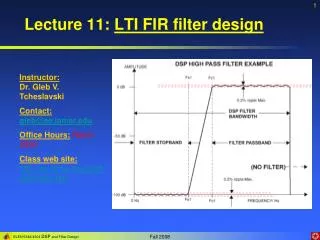
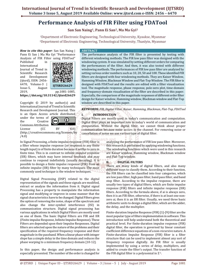
International Journal of Trend in Scientific Research and Development (IJTSRD) Volume 3 Issue 5, August 2019 Available Online: www.ijtsrd.com e-ISSN: 2456 – 6470 Performance Analysis of FIR Filter using FDATool San San Naing1, Pann Ei San2, Ma Ma Gyi1 1Department of Electronic Engineering, Technological University, Kyaukse, Myanmar 2Department of Electronic Engineering, Technological University, Thanlyin, Myanmar How to cite this paper: San San Naing | Pann Ei San | Ma Ma Gyi "Performance Analysis of FIR Filter using FDATool" Published in International Journal of Trend in Scientific Research and Development (ijtsrd), ISSN: 2456- 6470, Volume-3 | Issue-5, August 2019, pp.1081-1085, https://doi.org/10.31142/ijtsrd26629 Copyright © 2019 by author(s) and International Journal of Trend in Scientific Research and Development Journal. This is an Open Access article distributed under the terms of the Creative Commons Attribution License (CC BY 4.0) (http://creativecommons.org/licenses/by /4.0) In Signal Processing, a finite impulse response (FIR) filter is a filter whose impulse response (or response to any finite length input) is of finite duration because it settles to zero in finite time. This is in contrast to infinite impulse response (IIR) filters, which may have internal feedback and may continue to respond indefinitely (usually decaying). It is possible to design a finite impulse response (FIR) from an infinite impulse (IIR) filter by many techniques. The most commonly used technique is the window techniques. Digital Signal Processing (DSP) related to the digital representation of the signals and these signals are modified, extract or analyze the information from it. Digital signal Processing has a property to manipulate the information signal and modifying or improve in some manner that the signal characteristics have to be changed. Digital Filters gives the option of removing the noise, shape of the spectrum and also change the inter-symbol interference (ISI) in communication structure. Digital signal processing has various applications in which Digital Filters are mostly used as one of them. The basic Digital Filters are FIR and IIR (Finite impulse Response, Infinite Impulse Response). These Filters are depended upon their Impulse Responses. Digital filters are selected upon the nature of the problems and their specification of the required frequency response and their magnitude in the passband. When a linear phase with integer slope has a simple delay in the time domain and reduces the phase warping to a minimum frequency domain [10-12]. In this paper, the design and performance analysis is especially presented. The number of the order is changed for ABSTRACT The performance analysis of the FIR filter is presented by testing with different windowing methods. The FIR low pass filter was designed with the windowing system. It was simulated by setting different orders for comparing the performances of the filter. And then, it was also tested with different windowing methods. The performances of FIR low pass filter are analyzed by setting various order numbers such as 10, 20, 50 and 100. These identified FIR filters are designed with four windowing methods. They are Kaiser Window, Hamming Window, Blackman Window and Flat-Top Window. The FIR filter is designed with FDATool and the results are edited with a filter visualization tool. The magnitude response, phase response, pole-zero plot, time-domain and frequency-domain visualization of the filter are described in this paper. Especially, the comparison of the magnitude responses of different order filter design for Kaiser window, Hamming window, Blackman window and Flat-Top window are described in this paper. KEYWORDS: FIR, Digital Filter, Kaiser, Hamming, Blackman, Flat-Top, FDATool I. INTRODUCTION Digital Filters are mostly used in today’s communication and computation. Digital filter plays an important role in today’s world of communication and computation. Without the digital filter, we cannot think about proper communication because noise occurs in the channel. For removing noise or cancellation of noise we use various type of digital filter. IJTSRD26629 analyzing the performance of FIR low pass filter. Moreover, this research is performed by applying windowing functions. The windowing functions which were used in this research are Kaiser window, Hamming window, Blackman window and Flat-Top window. II. DIGITAL FILTERS There are many kinds of digital filters, and also many different ways to classify them. According to their function, the FIR filters can be classified into four categories, which are low pass filter, high pass filter, band pass filter, and band stop filter. According to the impulse response, there are usually two types of digital filters, which are finite impulse response (FIR) filters and infinite impulse response (IIR) filters. According to the formula above, if ai is always zero, then it is an FIR filter, otherwise, if there is at least one non- zero ai, then it is an IIR filter. Usually, we need three basic arithmetic units to design a digital filter, which are the adder, the delay, and the multiplier. Finite-duration Impulse Response (FIR) [1]-[9] filter are the most popular type of filters implementation in software. This introduction will help understand both the theoretical and practical level. For finite-duration impulse response (FIR) digital filter, the operation is governed by linear constant coefficient difference equations of a non-recursive nature. A Finite-duration Impulse Response (FIR) filter is a filter structure that can be used to implement almost any sort of frequency response digitally. An FIR filter is usually implemented by using a series of delay, multipliers, and added to create the filter’s output. The transfer function of the FIR digital filter is a polynomial in Z-1. @ IJTSRD | Unique Paper ID – IJTSRD26629 | Volume – 3 | Issue – 5 | July - August 2019 Page 1081
International Journal of Trend in Scientific Research and Development (IJTSRD) @ www.ijtsrd.com eISSN: 2456-6470 The following list gives some of the main advantages of digital over analog filters. 1.A digital filter is programmable, i.e. its operation is determined by a program stored in the processor's memory. This means the digital filter can easily be changed without affecting the circuitry (hardware). An analog filter can only be changed by redesigning the filter circuit. 2.Digital filters are easily designed, tested and implemented on a general-purpose computer or workstation. 3.The characteristics of analog filter circuits (particularly those containing active components) are subject to drift and are dependent on temperature. Digital filters do not suffer from these problems, and so are extremely stable with respect both to time and temperature. 4.Unlike their analog counterparts, digital filters can handle low-frequency signals accurately. As the speed of DSP technology continues to increase, digital filters are being applied to high-frequency signals in the RF (radio frequency) domain, which in the past was the exclusive preserve of analog technology. 5.Digital filters are very much more versatile in their ability to process signals in a variety of ways; this includes the ability of some types of the digital filter to adapt to changes in the characteristics of the signal. 6.Fast DSP processors can handle complex combinations of filters in parallel or cascade (series), making the hardware requirements relatively simple and compact in comparison with the equivalent analog circuitry. FIR Linear phase Filter order is high for given specifications A large number of the coefficient are used No feedback loop (non-recursive) Low precision III. FIR Filter Design The digital filter can be designed and implemented by applying the following steps: 1.Make sure of the property of a digital filter according to the given requirements. 2.Use a discrete linear time-invariant system function to approach to the properties. 3.Make use of algorithms to design the system function. 4.Use a computer simulation or hardware to achieve it. FIR filters are mostly used for application where exact linear phase response is required. The FIR used in a non- recursive way which is mostly a stable filter. FIR filter design essentially consists of Approximation problem and Realization. Approximation method chooses the ideal response from frequency domain also allowed the class of filters is chosen (e.g. the length N for filters). Approximation method or algorithm is used to find the best filter transfer function [13]. The realization part helps to choose the structure to implement the transfer function which may be in the form of a program. FIR filter designed by three well-known methods namely as Window method, Frequency sampling technique, Optimal filter design method. The window technique describes the various method of designing the FIR filter. In window techniques, the frequency responses of digital filters are periodic in frequency ranges and could be expanded in Fourier series. Kaiser window function: The Kaiser window is described by the formula (1) For n = 0:1: L-1, where L is the window length, M = (L-1)/2, and I0 represents the modified Bessel function of the first kind. Hamming window function: The causal hamming window function is defined by (2) (3) Blackman window function: The Blackman window function is described as follow: (4) The specifications used in this task are listed in following table. Specifications of FIR Low pass Filter Type Digital Filter FIR Structure Direct Form I Response Low pass Filter Filter Orders 10,20,50,100 Kaiser Window, Hamming Window, Blackman Window, Flat-Top IV. RESULTS OF FIR FILTER This paper presents the operations of the digital FIR filter. They are tested by changing the different windowing method such as Kaiser window, Hamming window, Blackman window and Flattop window. Moreover, it is simulated by varying the number of order in order to see the operation of the FIR filter. The results of the magnitude response for FIR filter with 10 order is shown in Fig 1. IIR Non-linear phase Filter order is low for given specification Less number of coefficients are required Have feedback loop (recursive) High Precision Description Design Methods Fig1. Magnitude Response of FIR Filter with 10 Order @ IJTSRD | Unique Paper ID – IJTSRD26629 | Volume – 3 | Issue – 5 | July - August 2019 Page 1082
International Journal of Trend in Scientific Research and Development (IJTSRD) @ www.ijtsrd.com eISSN: 2456-6470 The phase response of the FIR filter with 10 order is shown in Fig 2. The design information of the FIR filter for the 10 order number is presented in Fig 5. Fig5. Design Information of Discrete-Time FIR Filter The results of the FIR filter operation with 20 order is shown in Fig 6, Fig 7, Fig 8. Fig2. Phase Response of FIR Filter with 10 Orders The pole-zero plot of FIR filter with 10 order is illustrated in Fig 3. Fig6. Magnitude Response of FIR Filter with 20 Orders Fig3. Pole-Zero Plot of FIR Filter with 10 Orders In Fig 3, the first plot of the first row is the pole-zero plot of Kaiser window, the second plot of the first row is that of Hamming window, the first plot of the second row is that of Blackman window and the second plot of the second row is that of Flat-Top window. The different pole-zero mapping can be visualized by applying the different windowing methods for 10 order FIR lowpass filter. The time-domain and frequency-domain of FIR filter with 10 order is described in Fig 4. Fig4. Time-Domain and Frequency-Domain of FIR Filter with 10 Order Fig8. Time-Domain and Frequency-Domain of FIR Filter with 20 Order @ IJTSRD | Unique Paper ID – IJTSRD26629 | Volume – 3 | Issue – 5 | July - August 2019 Page 1083
International Journal of Trend in Scientific Research and Development (IJTSRD) @ www.ijtsrd.com eISSN: 2456-6470 Fig7. Phase Response of FIR Filter with 20 order Similarly, the operation of the FIR filter can be analyzed for many order system. In this paper, the operation of the FIR filter can be tested with 50 orders by applying different windowing system. The magnitude response, phase response and the matching of time-domain and frequency- domain are depicted in Fig 9, Fig 10 and Fig 11. Fig11. Time-Domain and Frequency-Domain of FIR Filter with 50 Order Finally, the operation of the FIR filter was analyzed for so many order system. In this paper, the operation of the FIR filter was also be tested with 100 orders by applying different windowing system. The magnitude response, phase response and the matching of time-domain and frequency- domain are depicted in Fig 12, Fig 13 and Fig 14. Fig9. Magnitude Response of FIR Filter with 50 Orders Fig10. Phase Response of FIR Filter with 50 orders Fig12. Magnitude Response of FIR Filter with 100 Orders Fig13. Phase Response of FIR Filter with 100 Orders @ IJTSRD | Unique Paper ID – IJTSRD26629 | Volume – 3 | Issue – 5 | July - August 2019 Page 1084
International Journal of Trend in Scientific Research and Development (IJTSRD) @ www.ijtsrd.com eISSN: 2456-6470 research. Although the Kaiser window has no ripple in the passband for lower-order number, it has significant ripple as the order number is increased to 50 and 100. In this situation, the Hamming window has no ripple in the passband. In addition, the transition width of the Hamming window is so little wider than the Kaiser window. Therefore, the Kaiser window is suitable for lower-order applications. For higher-order applications, the Hamming window is more suitable. Nevertheless, all window function has a linear phase and stability. VI. ACKNOWLEDGMENTS The author would like to thank all her teachers, parents and colleagues who support the help in their job. She also wants to express special thanks to her all family members. Moreover, she also expresses special thanks to all people who shared knowledge for this research. VII. REFERENCES [1]http://www.mikroe.com/chapters/view/72/chapter- 2fir-filters/ [2]Vinay K. Lngle, John G. Proakis, Digital Signal Processing using MATLAB. [3]John G. Proakis, Dimitris G. Manolakis, Digital Signal Processing: Principles’, Applications,4th edition. Algorithms, and [4]http://www.mathworks.com/help/dsp/examples/desi gninglow-pass-fir-filters.html [5]https://ccrma.stanford.edu/~jos/fp/Simplest_Lowpas s_Filter.ht ml [6]http://www.arc.id.au/FilterDesign.html [7]http://www.wavemetrics.com/products/igorpro/data analysis/signalprocessing/digitalfilters.htm [8]Mahrokh G. Shayesteh and Mahdi Mottaghi-Kashtiban “FIR filter design using a new window function” 978-1- 4244-32981/09, 2009 IEEE. [9]Chonghua Li, “Design and Realization of FIR Digital Filters Based on MATLAB” , IEEE 2010. [10]Emmanual C Ifeachor, Berrie W. Jervis, “Digital Signal Processing”, Pearson Education, pp. 2-4, 2002. [11]Shruti Jain, Dinesh Kumar Verma, “Comparison of various window functions used in FIR filter designing”, International Journal of Computer and Technology, Vol.8, No.3, pp. 902-907, 30 June 2013. Fig14. Time-Domain and Frequency-Domain of FIR Filter with 100 Orders V. The FIR low pass filter was designed by applying the different window functions such as Kaiser window, Hamming window, Blackman window and Flat-Top window. And it was also designed with Direct Form I structure. The performance of the FIR filter was tested by varying the number of orders. The performance results of that filter are presented with magnitude response, phase response, pole- zero plot, time-domain and frequency-domain visualization. According to the results, the performance of Kaiser window function has the narrower transition bandwidth than other functions and the Flat-Top window has the widest transition width for all number of orders which were used in this CONCLUSION [12]Aparna Tiwari, Vandana Thakre, Karuna Markam, “Performance Analysis of FIR Digital High Pass Filters”, International Journal of Computer & Communication Engineering Research, Vol. 2, pp. 89-92, 2 March 2014. [13]Sonika Gupta, Aman Panghal, “Performance analysis of FIR filter design by using Rectangular, Hamming and Hanning window method” International Journal of Advanced Research in Computer Science and Software Engineering, Vol.2, pp. 273-277, 6 June 2012. @ IJTSRD | Unique Paper ID – IJTSRD26629 | Volume – 3 | Issue – 5 | July - August 2019 Page 1085