Download
1 / 19
190 likes | 196 Views
At the point of convergence of any power system AC load flow iterative method, the principal bus parameters necessary to compute the transmission line flows and losses are provided. The exactness and accuracy of the result depends largely on the iterative method and the iteration termination criteria and each operating condition requires a unique solution of the analysis. State estimation techniques are also viable alternatives to AC load flow techniques in estimating network bus parameters from a known state but the speed of estimation is comparatively similar to the AC counterpart. However, the justification for the use of DC load flow for quick estimation of transmission line flows as against the AC is that the resulting mismatch is negligible when used for contingency and security analyses. Estimates of transmission line active power flow can be made using linear distribution sensitivity factors whose result match those of DC load flow. These sensitivity factors Power Transfer Distribution Factors PTDF and Line Outage Distribution Factors LODF are calculated and stored for a network and remains valid if the network remains significantly unmodified. With these stored factor from an operating point, post contingency flows may be predicted on any line. In this work, the PTDF and LODF of the Nigerian 330kV of 41 bus were computed and stored from a base case, then post contingency flows were predicted for the 77 transmission lines of the network following contingency in the form of 140MW load shedding at bus 1, 50 generator output reduction at bus 2, 100MW generator output increment at bus 20 and 100MW generator output decrease at bus 25. The result shows that using sensitivity factors to estimate transmission line flow works as validated by the result from load DC load flow technique. Therefore, a quicker, linear and non iterative method is validated in order to estimate transmission line flows from a known operating point with the slack bus responsible for active power exchanges. Emmanuel. A. Anazia | Onyedikachi N. Samuel` | Obroh O. Rebecca "Estimating Nigerian Power System Post Contingency Line Flows Using Power Distribution Factors" Published in International Journal of Trend in Scientific Research and Development (ijtsrd), ISSN: 2456-6470, Volume-2 | Issue-6 , October 2018, URL: https://www.ijtsrd.com/papers/ijtsrd18854.pdf Paper URL: http://www.ijtsrd.com/engineering/electrical-engineering/18854/estimating-nigerian-power-system-post-contingency-line-flows-using-power-distribution-factors/emmanuel-a-anazia<br>

E N D
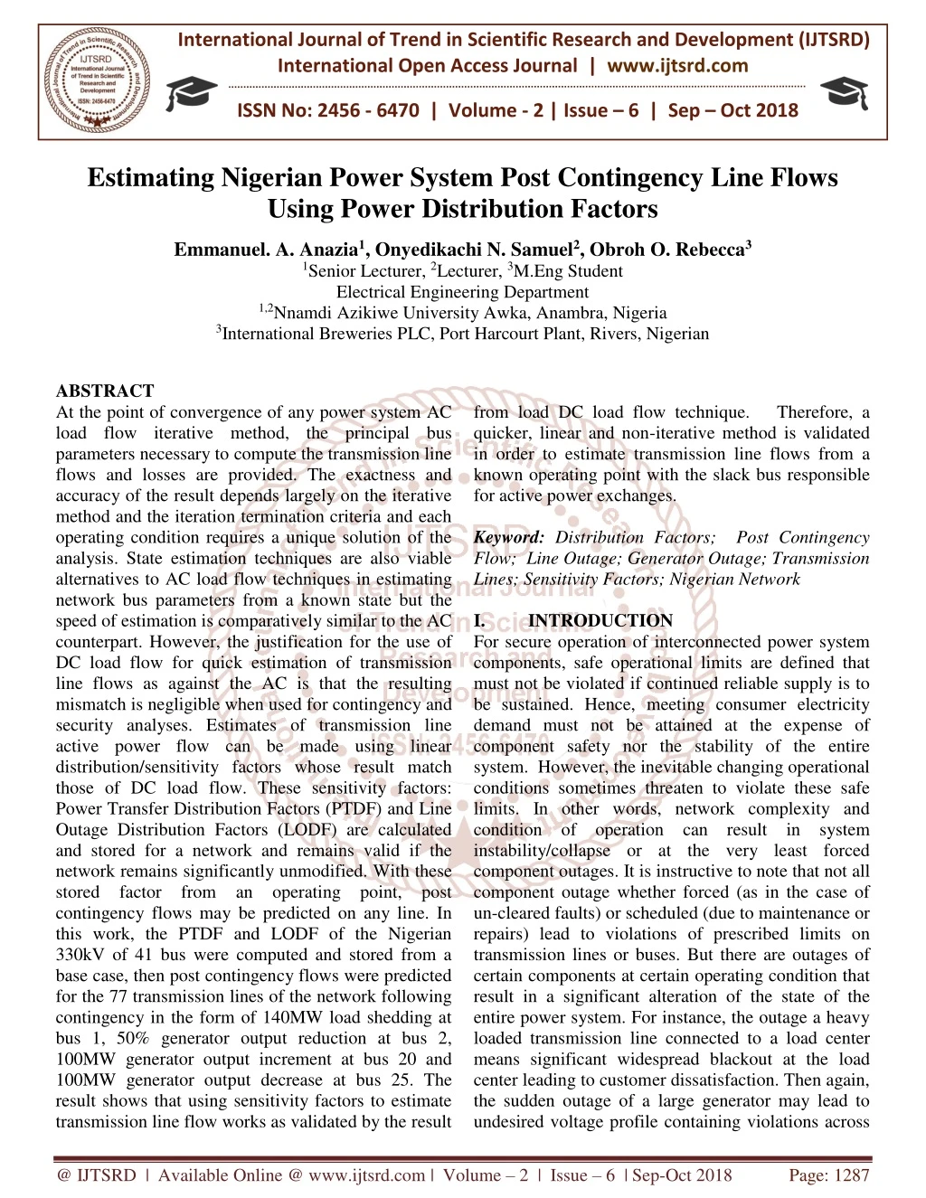
International Journal of Trend in Scientific Research and Development (IJTSRD) International Open Access Journal | www.ijtsrd.com ISSN No: 2456 - 6470 | Volume - 2 | Issue – 6 | Sep – Oct 2018 Estimating Nigerian Power System Post Contingency Line Flows Using Power Distribution Factors Emmanuel. A. Anazia1, Onyedikachi N. Samuel2, Obroh O. Rebecca3 1Senior Lecturer, 2Lecturer, 3M.Eng Student Electrical Engineering Department 1,2Nnamdi Azikiwe University Awka, Anambra, Nigeria 3International Breweries PLC, Port Harcourt Plant, Rivers, Nigerian ABSTRACT At the point of convergence of any power system AC load flow iterative method, the principal bus parameters necessary to compute the transmission line flows and losses are provided. The exactness and accuracy of the result depends largely on the iterative method and the iteration termination criteria and each operating condition requires a unique solution of the analysis. State estimation techniques are also viable alternatives to AC load flow techniques in estimating network bus parameters from a known state but the speed of estimation is comparatively similar to the AC counterpart. However, the justification for the use of DC load flow for quick estimation of transmission line flows as against the AC is that the resulting mismatch is negligible when used for contingency and security analyses. Estimates of transmission line active power flow can be made using linear distribution/sensitivity factors whose result match those of DC load flow. These sensitivity factors: Power Transfer Distribution Factors (PTDF) and Line Outage Distribution Factors (LODF) are calculated and stored for a network and remains valid if the network remains significantly unmodified. With these stored factor from an operating point, post contingency flows may be predicted on any line. In this work, the PTDF and LODF of the Nigerian 330kV of 41 bus were computed and stored from a base case, then post contingency flows were predicted for the 77 transmission lines of the network following contingency in the form of 140MW load shedding at bus 1, 50% generator output reduction at bus 2, 100MW generator output increment at bus 20 and 100MW generator output decrease at bus 25. The result shows that using sensitivity factors to estimate transmission line flow works as validated by the result from load DC load flow technique. Therefore, a quicker, linear and non-iterative method is validated in order to estimate transmission line flows from a known operating point with the slack bus responsible for active power exchanges. Keyword: Distribution Factors; Post Contingency Flow; Line Outage; Generator Outage; Transmission Lines; Sensitivity Factors; Nigerian Network I. INTRODUCTION For secure operation of interconnected power system components, safe operational limits are defined that must not be violated if continued reliable supply is to be sustained. Hence, meeting consumer electricity demand must not be attained at the expense of component safety nor the stability of the entire system. However, the inevitable changing operational conditions sometimes threaten to violate these safe limits. In other words, network complexity and condition of operation can result in system instability/collapse or at the very least forced component outages. It is instructive to note that not all component outage whether forced (as in the case of un-cleared faults) or scheduled (due to maintenance or repairs) lead to violations of prescribed limits on transmission lines or buses. But there are outages of certain components at certain operating condition that result in a significant alteration of the state of the entire power system. For instance, the outage a heavy loaded transmission line connected to a load center means significant widespread blackout at the load center leading to customer dissatisfaction. Then again, the sudden outage of a large generator may lead to undesired voltage profile containing violations across @ IJTSRD | Available Online @ www.ijtsrd.com | Volume – 2 | Issue – 6 | Sep-Oct 2018 Page: 1287
International Journal of Trend in Scientific Research and Development (IJTSRD) ISSN: 2456-6470 a number of nodes which may culminate in voltage collapse. In other words, each components outage has a unique implication which is largely dependent on the component defined limits, its role and the condition of system operation. comprehensive knowledge components and their condition of operation at the levels of design, planning and operation is indispensible for reliable supply and to this end, stability assessment methods are employed. One of such methods is sensitivity analysis which measures the sensitivity of a line component with respect to an outage or variation of flow on another transmission line or from generator at a node. II. SENSITIVITY ANALYSIS The word sensitivity is defined to be the degree of response of a system, to a change in the input signal. An extended definition with respect to power system network would mean that sensitivity analysis of power grid components is the process of determining the impact or effect on a particular system variable will cause and how it would vary from a known or desired state [1]. This enables the system planner or operator, to determine how the entire system would respond to a change and in this case an outage forced or scheduled. With respect to this, the pertinent questions are: is it possible to estimate a post- contingency power flow on transmission lines? Is it also possible to estimate power system defined limit violations and estimate the margin to violation from a current operational state following a viable grid component contingency? Such capability makes it possible to screen and select credible contingencies from a pool of possible contingencies, rank them on the bases of their severity and/or the number of violations they cause. This screening and ranking would enable remedial or preventive actions to be recommended or implemented to ameliorate the impact of such credible violation. A.Distribution Factors The problem of studying thousands of possible outages becomes herculean if the desire is to present quick results. However, one of the easiest ways to provide a quick calculation of possible overloads is to use linear sensitivity factors [2]. Since generators are the source of real power while transmission lines are the conveyors to the load centers, there is need to ascertain system sensitivities to the flows through these lines, especially when the output of the generator vary within network. Again since generator outputs and line flows of real power are summative, linear analysis involving direct current manipulations seem adequate especially for a lossless network. Linear sensitivity factors are preferred on the account of the ease and speed of calculation of possible overloads especially when studying numerous possible outages [3]. Power distribution factor is about the only technique used in allocating MW flows on the lines for power transaction in the system defines the relative change in the power flow on a particular line due to an injection or withdrawal of power on a pair of buses while line outage distribution factors are linear estimates of the change in flow on adjacent lines with the outage of transmission lines. Basically, they are of two types; 1.Power Transfer Distribution Factors (PTDF) PTDF shows linearized impact of power transfer [4]. It is the relative change in power flow on a particular line due to an injection and withdrawal of power on a pair of buses [5]. They represent the sensitivity of the flow on line ? to a shift of power from bus ? to bus ? [2]. Power Transfer Distribution Factors are also known by other names such as Generation Shift Factors (GSFs), Power Distribution Coefficients (PDCs), Effectiveness Factors and Impedance Factors. The PTDF has four (4) attributes, namely; ➢a particular Line (with reference direction) ➢a particular Bus ➢value of the transfer factor ➢a reference bus The value of the PTDF of line ? with respect to bus ? is defined to be the change (or sensitivity) of active megawatt (MW) power flow in a reference direction on line ? with respect to a change in injection at bus ? and a corresponding change in withdrawal at the reference bus [6]. PTDF has the following mathematical expression as [7] ∆?? ∆?? ?? ? (1) ?????,?,? = PTDF for power transfer from bus ? to bus ∆?? = change in line flow of the monitored line when power is ∆?? ?? ? = power transferred from bus ? to bus ? Numerical range of PTDF includes: −1 ≤ ?????,?,?≤ +1 Therefore, the a of network ?????,?,?= ? transferred @ IJTSRD | Available Online @ www.ijtsrd.com | Volume – 2 | Issue – 6 | Sep-Oct 2018 Page: 1288
International Journal of Trend in Scientific Research and Development (IJTSRD) ISSN: 2456-6470 1.Estimating the power flow sensitivity of network transmission lines outages/output variation. 2.Estimating the power flow sensitivity of network transmission lines due to the outage of adjacent transmission lines. 3.Estimating post-outage transmission line active power flows 4.Verifying the post-contingency Active power flows estimated from sensitivity factors using post-contingency DC load-flow results. The network used for this estimation is the Nigerian 330KV power system network consisting of 41 buses, 17 generators and 77 transmission lines. The network generator/bus data and line parameters are given in the appendix section. A.Procedure: 1.Derive relationships for AC and DC load flows 2.Estimate the Transmission line flows for AC and DC methods for the network at a base case. 3.Following any contingency; transmission line outage, reduction/increase or total outage of generation at any generator (beside the Slack bus), estimate the DC line flows for all the transmission lines of the network. 4.Derive the equations representing the sensitivity factors; PTDF and LODF and for the network, evaluate the values of PTDF and LODF. 5.Using PTDF and LODF values, estimate transmission flow for a monitored line with respect to generation reduction, increase or outage and line outage. 6.For a monitored line, compare the estimated flow of (v) to the flows of (iii) above. Executable MATLAB programs have been used to perform the AC load flow (Newton Raphson iteration), DC load flow, PTDF and LODF estimations. Predicting Post contingency flow using B.Mathematical Descriptions Direct Current (DC) Load Flow of Sample Network Unlike the AC load flow, the DC power flow is a non- iterative as it simplifies the Fast decoupled AC derivations under certain assumptions. Following these assumptions, the predominant relationship from the Fast decoupled method [12] relates ∆? and ∆?, expressed as ?????,?,?= 1, this is an indication that all of the transferred power from ? to ? must flow through line l. If the value is −1, it means that all of the transferred power from ? to ? will flow through line l, but in a reversed direction and if ?????,?,?= 0, this indicates that none of the power transferred from ? to ? will pass through line l [8]. 2.Line Outage Distribution Factor (LODF) Line outage distribution factors are linear estimates of the change in flow on adjacent lines when transmission lines are lost [9]. They are often applied in checking overloads on the lines following the line loss [10]. The failure/outage of a major transmission line causes redistribution in the line flows and can result in voltage variation within the system. The analysis of transmission line failures requires methods to predict these line flows and voltages. LODF shows linearized impact of power transfer. They represent the sensitivity of the flow on line ? to a line failure in the network [2]. LODFs aids in calculating the impact the opening (outage) of a transmission line will have on all the other lines in the power system. The value of the LODF of line ? with respect to loss of line ? is defined to be the change (or sensitivity) of active (MW) power flow on line ? with line ? out. A simulation program was used to study the cases of line outages in the system using the line outage distribution factors [11]. Outages of lines which cause increased power flow over prescribed limit in the remaining lines of the network are detected. The LODF factors are given as [7]; ?????,?= ∆?? ??0 (2) ?????,?= line outage distribution factor when monitoring line ? after an outage on line ? ∆??= change in MW flow on monitored line ? ??0= original flow on outage (open) line ? III. METHODOLOGY The aim of this work is to estimate post-contingency on the Nigerian 330kV transmission line flows using direct current based sensitivity factors. This would be achieved by due to generators @ IJTSRD | Available Online @ www.ijtsrd.com | Volume – 2 | Issue – 6 | Sep-Oct 2018 Page: 1289
International Journal of Trend in Scientific Research and Development (IJTSRD) ISSN: 2456-6470 ∆?1 ∆?2 ⋮ ∆?1 ∆?2 ⋮ ] = [?′][ ] (3) [ ∆?(?−1) ∆?(?−1) ∆?1 |?1| ∆?2 |?2| ⋮ ?1(?−1) ?2(?−1) ⋮ ?(?−1)(?−1) ∆?1 ∆?2 ⋮ ?11 ?21 ⋮ ?12 ?22 ⋮ ⋯ ⋯ ⋮ ⋯ ] (4) = [ ][ ?(?−1)1 ?(?−1)2 ∆?(?−1) ∆?(?−1) |?(?−1)|] [ Where the diagonal and off diagonal of the reactance matrix B is ???= ∑ ??? ?=1 But where ?, the resistance of the transmission line is significant, then ???= ∑ −??? ?=1 and ???= ???= − The DC load flow is adequate in estimating approximately accurate MW flows on transformers and transmission lines while ignoring the MVAR and MVA flows. Consequently, form [2], the real or MW power flow on a lossless transmission line connected between bus ? and bus ? using DC power flow is ???= ? ??? ? ????????? ??? ??????? (1,2,3,4,…,?) Note that ???= −??? Then the Power scheduled at ??? ?, ?? is derived using ? (6) ??? = reactance of line between bus ? and bus ? ?? =Calculated Real power schedule at bus ? and ? respectively ???= Real power flowing through transmission line connected between bus ? and bus ? ??& ??= Voltage bus angle at bus ? and ? respectively The power network used here is the Nigerian 330kV interconnected network. This version of the network contains 41 buses, 17 generators and 30 load units which are interconnected by 77 transmission lines. The total system base load is 7491 MW and the generator at bus 27 (Egbin) is used as slack/reference generator. The network oneline diagram is shown below while its network data with respect to bus, generator and line parameters are given in appendix tables 4.13, 4.14 and 4.15 respectively). In order to justify the choice of the DC over the AC flow estimation, we compare the AC and DC MW flows of the network at base case; noting how marginal the mismatch is. 1 1 ???? and ???= ???= − ??? ??? 2+??? ???? 2 ??? 1 ???(??− ??) (5) ??= ∑??? ?=1 @ IJTSRD | Available Online @ www.ijtsrd.com | Volume – 2 | Issue – 6 | Sep-Oct 2018 Page: 1290
International Journal of Trend in Scientific Research and Development (IJTSRD) ISSN: 2456-6470 mando 8 9 15 14 damaturu kebbi 1 maiduguri kainji Gs 2 yola 12 35 34 6 4 3 11 jebba 7 10 markurdi 36 33 jos shiroro Gs new.h katampe 32 oshogbo 5 ayede 21 13 onitsha ikeja.w 25 17 23 geregu benin 19 okpai omotosho 16 30 24 alaoji egbin 27 18 afam 29 slack 38 akangba 40 ikot ekpene owerri Aja 26 delta 22 egbema 41 37 omoku 28 39 aladja calabar Figure 1: The Nigerian 330kV 41 bus system Table 1: Base Case MW Flow Mismatch from AC and DC Load Flow Analysis Line MW flow Mismatch Actua l -150 -150 0 0.00 Line Cod e L1 Bus From- To 1-2 Line Cod e L40 Bus From- To 18-17 Line MW flow Mismatch Actua l 0.07 AC DC % AC DC % 146.93 147 0.05 L2 2-3 223.76 225 1.24 0.55 L41 19-18 197 197 0 0.00 L3 2-3 223.76 225 1.24 0.55 L42 19-18 197 197 0 0.00 L4 3-4 476.38 437.91 38.47 8.08 L43 21-30 74.23 - 315.32 57 17.23 23.21 L5 3-4 476.38 437.91 38.47 8.08 L44 21-31 -320 4.68 1.48 - L6 3-5 -91.94 27.98 23.33 L45 21-32 552.04 504.11 47.93 8.68 119.92 - 119.92 - 119.92 L7 3-5 -91.94 27.98 23.33 L46 22-28 370.28 371.62 1.34 0.36 L8 3-5 -91.94 27.98 23.33 L47 23-16 305.5 300 5.5 1.80 - - L9 6-3 250 250 0 0.00 L48 23-17 57.72 25.74 224.26 - 224.26 - 277.23 - 277.23 -235 281.98 - 281.98 - 176.06 - 176.06 -235 L10 6-3 250 250 0 0.00 L49 23-17 57.72 25.74 101.1 7 101.1 7 0 L11 4-7 177.04 175 2.04 1.15 L50 23-27 36.49 L12 4-7 177.04 175 2.04 1.15 L51 23-27 36.49 L13 4-8 293.88 275.41 18.47 6.28 L52 24-23 0.00 @ IJTSRD | Available Online @ www.ijtsrd.com | Volume – 2 | Issue – 6 | Sep-Oct 2018 Page: 1291
International Journal of Trend in Scientific Research and Development (IJTSRD) ISSN: 2456-6470 L14 4-8 293.88 275.41 18.47 - 178.22 174.91 - 178.22 174.91 - 178.22 174.91 6.28 L53 24-23 -235 -235 0 0.00 - L15 5-17 3.31 1.86 L54 25-23 72.32 95.16 22.84 31.58 - L16 5-17 3.31 1.86 L55 27-26 227.86 227.5 0.36 0.16 - L17 5-17 3.31 1.86 L56 27-26 227.86 227.5 0.36 0.16 288.1 1 107.1 1 2.22 L18 5-23 11.61 45.06 33.45 L57 28-20 66.7 69.62 2.92 4.38 L19 5-33 -40.25 2.86 43.11 L58 29-37 210.34 201.74 8.6 4.09 L20 8-9 357.95 350 7.95 L59 29-38 127.48 123.72 3.76 2.95 L21 8-10 73.9 66.94 6.96 9.42 L60 29-38 127.48 123.72 3.76 2.95 105.3 6 105.3 6 0.61 L22 8-10 73.9 66.94 6.96 9.42 L61 30-29 7.65 -0.41 8.06 L23 8-10 73.9 66.94 6.96 9.42 L62 30-29 7.65 -0.41 8.06 L24 10-11 288.68 269.38 - 159.34 - 159.34 19.3 6.69 L63 30-40 49.3 49 0.3 - L25 10-36 0.06 0.04 L64 30-40 49.3 49 0.3 0.61 159.28 - 159.28 - - L26 10-36 0.06 0.04 L65 32-38 3.75 1.31 285.84 - 285.84 - 148.85 -31.38 282.09 - 282.09 L27 12-11 -160 -160 0 0.00 L66 32-38 3.75 1.31 L28 13-23 120.69 142.7 22.01 18.24 L67 33-13 -127.3 21.55 14.48 L29 14-11 40.49 50.62 10.13 25.02 L68 33-25 -8.84 22.54 71.83 L30 14-15 201.83 - 372.32 - 145.35 - 320.01 - 320.01 - 320.01 200 - 380.62 1.83 0.91 L69 35-8 200 - 444.33 - 444.33 200 - 439.15 - 439.15 0 0.00 L31 14-34 8.3 2.23 L70 36-32 5.18 1.17 L32 17-18 -147 1.65 1.14 L71 36-32 5.18 1.17 - L33 17-20 3.2 1.00 L72 36-34 192.76 189.87 2.89 1.50 323.21 - 323.21 - 323.21 L34 17-20 3.2 1.00 L73 36-34 192.76 189.87 2.89 1.50 L35 17-20 3.2 1.00 L74 37-38 154.24 146.74 7.5 4.83 - L36 17-21 142.96 118.77 24.19 16.92 L75 38-39 -155 0.69 0.45 154.31 - 154.31 -81.6 L37 17-21 142.96 118.77 24.19 16.92 L76 38-39 -155 0.69 0.45 L38 17-21 142.96 118.77 24.19 - 335.56 338.38 16.92 L77 40-41 -82 0.4 0.49 - L39 17-22 2.82 0.84 @ IJTSRD | Available Online @ www.ijtsrd.com | Volume – 2 | Issue – 6 | Sep-Oct 2018 Page: 1292
International Journal of Trend in Scientific Research and Development (IJTSRD) ISSN: 2456-6470 VI. A.Evaluating PTDF and LODF The process began by defining an operating point (also called the Base Case: BC) of the network. Subsequently, the DC MW flow and the linear sensitivity factors from this operating point (BC) are evaluated and stored. Table 1 gives the DC line flows for all 77 transmission line at the defined base case. The PTDF of 40 buses with respect to the slack bus (bus 27) while LODF of the 77 transmission lines can be calculated at this operating condition. The size of the resulting PTDF and LODF matrices cannot be reflected in this publication being 17 by 77 and 77 by 77 respectively. However, evaluating PTDF and LODF can be demonstrated. To this end, as table 2 shows, buses 2 and line 8 were chosen to demonstrate how PTDF and LODF of the 77 transmission lines are calculated. Using equation 1, restated as ?????,?,?= ∆?? ∆?? ?? ? (7) ??0 & ??̂∶ Pre and Post generator outage MW flow on line ? (? = 1,2,…77) ∆??= ??̂− ??0 : Change in MW flow of the monitored line when power is transferred ∆?? ?? ?: Power transferred from Outage bus ? = 2 to the Reference bus ? = 27 Considering generator at bus 2, its pre-outage output is 600MW, the post outage output is 0MW. ∆?2 ?? 27= 0 − 600 = −600MW. This is the power which the reference bus 27 now delivers at post- outage. If we were to monitor line ? = 4, then from table 1, the pre-outage flow ?40= 437.9??, post-outage flow ?4̂= 400.3?? ????2,27,4=?4̂− ?40 ∆?2 ?? 27 = 0.062667 Similarly, RESULT AND DISCUSSION ??0=??̂− ??0 ?????,?= ∆?? (8) ??0 ??0 & ??̂∶ Pre and Post outage MW flow on line ? (? = 1,2,…77) ∆??= ??̂− ??0: Change in MW flow on monitored line ? ??0= original flow on outage (open) line ? From Table 1, consider line ? = 8, the pre-outage MW flow is -91.94MW ( but actually flowing from bus 5 to bus 3). If we monitor line ? = 4, its pre- outage flow ?40= 437.9??, and following the outage of line ? = 8, the post outage flow on line ? = 4; ?4̂= 432.8??. Then, ????4,8=?4̂− ?40 ?8 The complete PTDF and LODF for the 77 lines with respect to bus 2 and line 8 is given in table 2. B.Predicting Post Contingency MW Flow from Sensitivity Factors When contingency occurs in terms of line outage or generator/load outage, generator output/load variation then the evaluated and stored base case MW line flows and the sensitivity factors may be used to predict the line MW flow without resorting to the tedious load flow or state estimation techniques. Using PTDF, the MW line flow following power variation at any bus compensated by the reference bus k is ??̂= ?????,?,?∗ ∆?? ?? ?+ ??0 (9) While the MW line flow following line outage using LODF is ??̂= ?????,?∗ ??0+ ??0 (10) Consider the following contingency conditions in table 4. Additionally, table 3 reports the PTDF with respect to buses 20 and 25 as well as the LODF with respect to lines 10, 15 and 49. ∆?=??̂− ??0 =432.8 − 437.9 −91.94 = 0.005547 0 =400.3 − 437.9 −600 @ IJTSRD | Available Online @ www.ijtsrd.com | Volume – 2 | Issue – 6 | Sep-Oct 2018 Page: 1293
International Journal of Trend in Scientific Research and Development (IJTSRD) ISSN: 2456-6470 Table 2: Calculating PTDF and LODF for Bus 2 and Line 8 Li ne Co de L1 L2 L3 Base Case flow Gen2 Outage Flow L8 Base Case flow Gen2 Outage Flow L8 LO DF PT DF LO DF Line Code PT DF Outage Flow Outage Flow -150.0 225.0 225.0 -150.0 -75.0 -75.0 0 -150.0 225.0 225.0 0 0 0 L40 L41 L42 147.0 197.0 197.0 147.0 197.0 197.0 0 0 0 - 147.0 197.0 197.0 0 0 0 - 0.5 0.5 0.0 63 0.0 56 L4 437.9 400.3 432.8 L43 57.2 78.0 0.0 35 60.0 0.0 31 0.0 63 0.0 56 L5 437.9 400.3 432.8 L44 -320.0 -320.0 0 -320.0 0 - - 0.2 92 0.4 44 L6 -91.9 -266.9 -132.8 L45 504.1 558.5 0.0 91 511.6 0.0 81 0.2 92 0.2 92 0.4 44 L7 -91.9 -266.9 -132.8 L46 371.6 371.6 0 371.6 0 L8 -91.9 -266.9 0.0 -1 L47 300.0 300.0 0 300.0 0 - - L9 250.0 250.0 0 250.0 0 L48 -282.0 -155.4 0.2 11 - 0.2 11 -280.5 0.0 16 - 0.0 16 L1 0 250.0 250.0 0 250.0 0 L49 -282.0 -155.4 -280.5 L1 1 L1 2 L1 3 L1 4 175.0 175.0 0 175.0 0 L50 -176.1 -476.1 0.5 -176.1 0 175.0 175.0 0 175.0 0 L51 -176.1 -476.1 0.5 -176.1 0 0.0 63 0.0 63 0.0 56 0.0 56 - 0.0 27 - 0.0 27 - 0.0 27 - 0.0 14 - 0.0 17 275.4 237.8 270.3 L52 -235.0 -235.0 0 -235.0 0 275.4 237.8 270.3 L53 -235.0 -235.0 0 -235.0 0 - L1 5 0.0 99 0.1 62 -174.9 -234.2 -172.5 L54 95.2 -2.0 96.0 0.0 09 L1 6 0.0 99 -174.9 -234.2 -172.5 L55 227.5 227.5 0 227.5 0 L1 7 0.0 99 -174.9 -234.2 -172.5 L56 227.5 227.5 0 227.5 0 L1 8 0.2 63 45.1 -112.4 46.4 L57 69.6 69.6 0 69.6 0 - - L1 9 0.3 16 2.9 -186.5 4.5 L58 201.7 210.5 0.0 15 - 0.0 1 202.9 0.0 13 - 0.0 09 L2 0 350.0 350.0 0 350.0 0 L59 123.7 129.8 124.6 @ IJTSRD | Available Online @ www.ijtsrd.com | Volume – 2 | Issue – 6 | Sep-Oct 2018 Page: 1294
International Journal of Trend in Scientific Research and Development (IJTSRD) ISSN: 2456-6470 - - L2 1 0.0 42 0.0 37 66.9 41.9 63.5 L60 123.7 129.8 0.0 1 - 0.0 17 - 0.0 17 124.6 0.0 09 - 0.0 16 - 0.0 16 L2 2 0.0 42 0.0 37 66.9 41.9 63.5 L61 -0.4 10.0 1.0 L2 3 0.0 42 0.0 37 66.9 41.9 63.5 L62 -0.4 10.0 1.0 L2 4 L2 5 L2 6 L2 7 0.0 22 0.0 52 0.0 52 0.0 2 0.0 46 0.0 46 269.4 256.0 267.6 L63 49.0 49.0 0 49.0 0 -159.3 -190.2 -163.5 L64 49.0 49.0 0 49.0 0 0.0 17 0.0 17 0.0 16 0.0 16 - 0.0 08 - 0.0 09 -159.3 -190.2 -163.5 L65 -282.1 -292.5 -283.5 -160.0 -160.0 0 -160.0 0 L66 -282.1 -292.5 -283.5 - L2 8 0.1 54 0.1 54 142.7 50.5 143.5 0.0 08 - 0.0 2 L67 -127.3 -219.6 -126.5 - L2 9 0.1 62 50.6 64.0 0.0 22 52.5 L68 -8.8 -106.0 -8.0 L3 0 L3 1 L3 2 200.0 200.0 0 200.0 0 L69 200.0 200.0 0 200.0 0 0.0 22 0.0 2 0.0 63 0.0 63 - 0.0 11 - 0.0 11 - 0.0 15 0.0 56 0.0 56 - 0.0 1 - 0.0 1 - 0.0 13 -380.6 -394.0 -382.5 L70 -439.2 -476.7 -444.3 -147.0 -147.0 0 -147.0 0 L71 -439.2 -476.7 -444.3 L3 3 -323.2 -323.2 0 -323.2 0 L72 189.9 196.6 190.8 L3 4 -323.2 -323.2 0 -323.2 0 L73 189.9 196.6 190.8 L3 5 -323.2 -323.2 0 -323.2 0 L74 146.7 155.5 147.9 - - L3 6 118.8 143.8 0.0 42 - 0.0 42 - 0.0 42 122.2 0.0 37 - 0.0 37 - 0.0 37 L75 -155.0 -155.0 0 -155.0 0 L3 7 118.8 143.8 122.2 L76 -155.0 -155.0 0 -155.0 0 L3 8 118.8 143.8 122.2 L77 -82.0 -82.0 0 -82.0 0 L3 9 -338.4 -338.4 0 -338.4 0 @ IJTSRD | Available Online @ www.ijtsrd.com | Volume – 2 | Issue – 6 | Sep-Oct 2018 Page: 1295
International Journal of Trend in Scientific Research and Development (IJTSRD) ISSN: 2456-6470 Table 3: Selected PTDF (Buses 20 & 25) and LODF (Line 10.15 & 49) LC Bus 20 Bus 25 L10 L15 L49 Bus 20 Bus 25 L10 L15 L49 LC L1 L40 0 0 0 0 0 0 0 0 0 0 L2 L41 0 0 0 0 0 0 0 0 0 0 L3 L42 0 0 0 0 0 0 0 0 0 0 L4 L43 -0.0204 0.0071 0 0.0565 0.0304 0.0113 -0.0039 0 -0.0313 -0.0168 L5 L44 -0.0204 0.0071 0 0.0565 0.0304 0 0 0 0 0 L6 L45 0.0136 -0.0047 0 -0.0377 -0.0202 0.0295 -0.0102 0 -0.0817 -0.0439 L7 L46 0.0136 -0.0047 0 -0.0377 -0.0202 -0.0803 0 0 0 0 L8 L47 0.0136 -0.0047 0 -0.0377 -0.0202 0 0 0 0 0 L9 L48 0 0 1 0 0 -0.3288 -0.0595 0 0.1647 0.4898 L10 L49 0 0 -1 0 0 -0.3288 -0.0595 0 0.1647 -1 L11 L50 0 0 0 0 0 0.5 0.5 0 0 0 L12 L51 0 0 0 0 0 0.5 0.5 0 0 0 L13 -0.0204 0.0071 L52 0 0.0565 0.0304 0 0 0 0 0 L14 -0.0204 0.0071 L53 0 0.0565 0.0304 0 0 0 0 0 L15 -0.1006 0.0349 L54 0 -1 0.1498 0.0959 0.5726 0 0.0923 -0.1429 L16 -0.1006 0.0349 L55 0 0.2788 0.1498 0 0 0 0 0 L17 -0.1006 0.0349 L56 0 0.2788 0.1498 0 0 0 0 0 L18 0.1555 L57 0.081 0 0.1496 -0.2317 -0.0803 0 0 0 0 L19 L58 0.187 -0.1999 0 0.1799 -0.2786 0.0048 -0.0016 0 -0.0132 -0.0071 L20 L59 0 0 0 0 0 0.0033 -0.0011 0 -0.0091 -0.0049 L21 -0.0136 0.0047 L60 0 0.0377 0.0202 0.0033 -0.0011 0 -0.0091 -0.0049 L22 -0.0136 0.0047 L61 0 0.0377 0.0202 0.0056 -0.002 0 -0.0157 -0.0084 L23 -0.0136 0.0047 L62 0 0.0377 0.0202 0.0056 -0.002 0 -0.0157 -0.0084 L24 -0.0072 0.0025 L63 0 0.0201 0.0108 0 0 0 0 0 L25 -0.0168 0.0058 L64 0 0.0465 0.025 0 0 0 0 0 L26 -0.0168 0.0058 L65 0 0.0465 0.025 -0.0056 0.002 0 0.0157 0.0084 @ IJTSRD | Available Online @ www.ijtsrd.com | Volume – 2 | Issue – 6 | Sep-Oct 2018 Page: 1296
International Journal of Trend in Scientific Research and Development (IJTSRD) ISSN: 2456-6470 L27 L66 0 0 0 0 0 -0.0056 0.002 0 0.0157 0.0084 L28 0.0911 L67 0.2274 0 0.0876 -0.1357 0.0911 0.2274 0 0.0876 -0.1357 L29 0.0072 -0.0025 L68 0 -0.0201 -0.0108 0.0959 -0.4274 0 0.0923 -0.1429 L30 L69 0 0 0 0 0 0 0 0 0 0 L31 -0.0072 0.0025 L70 0 0.0201 0.0108 -0.0204 0.0071 0 0.0565 0.0304 L32 L71 0 0 0 0 0 -0.0204 0.0071 0 0.0565 0.0304 L33 -0.3066 L72 0 0 0 0 0.0036 -0.0013 0 -0.01 -0.0054 L34 -0.3066 L73 0 0 0 0 0.0036 -0.0013 0 -0.01 -0.0054 L35 -0.3066 L74 0 0 0 0 0.0048 -0.0016 0 -0.0132 -0.0071 L36 0.0136 -0.0047 L75 0 -0.0377 -0.0202 0 0 0 0 0 L37 0.0136 -0.0047 L76 0 -0.0377 -0.0202 0 0 0 0 0 L38 0.0136 -0.0047 L77 0 -0.0377 -0.0202 0 0 0 0 0 L39 -0.0803 0 0 0 0 Table 4: Contingency definition for Post Contingency Flow Prediction Contingency Definition Location Pre-contingency Post-Contingency 50% output Reduction Bus 2 100MW output Increment Bus 20 100MW output Reduction Bus 25 140 MW Load Reduction Bus 1 *The change with respect to load is positive, unlike generator. MW Output Exchanged Power -300 100 -100 140* Slack bus action supply more supply less supply more supply less 600 900 304 150 300 1000 204 10 From the base case and proceed with these mutually exclusive contingencies. Let’s assume that the load center at bus 1 reduced its demand from the base case of 150MW to 10MW or that the outputs at generator buses 2, 20 and 25 were varied as stated on the table; the idea is to predict the MW flow on any or all of the transmission lines without resort to state estimation or load flow. In order to accomplish this, we need information of the flow at any operation and the corresponding linear sensitivity factors. If we decide to predict the flows on line 54, when any of the contingencies of table 4 occur, then we would need the Pre-outage flow on the monitored line ??0= 95.16??, The power exchanged between the contingency bus and the reference bus: (5th column) of table 4 The corresponding sensitivity factors, (PTDF) of line 54 with respect to the contingency bus 1, bus 2, bus 20 and bus 25 which are 0.1619, 0.162, 0.0959 and 0.5726 respectively. Bus 1: ?54 ̂= ????1,27,54∗ ∆?1 ?? 27+ ?54 = 0.1619 ∗ (150 − 10) + 95.16 = 117.826?? Bus 2: ?54 ̂= ????2,27,54∗ ∆?2 ?? 27+ ?54 = 0.162 ∗ (300 − 600) + 95.16 = 46.56?? 0 0 @ IJTSRD | Available Online @ www.ijtsrd.com | Volume – 2 | Issue – 6 | Sep-Oct 2018 Page: 1297
International Journal of Trend in Scientific Research and Development (IJTSRD) ISSN: 2456-6470 = 37.90?? Notice that the values of flow estimated from PTDF match the DC load flow output reported in table 6. 0 ̂= ????20,27,54∗ ∆?20 ?? 27+ ?54 Bus 20: ?54 = 0.0959 ∗ (1000 − 900) + 95.16 = 104.75?? Bus 25: ?54 ̂= ????25,27,54∗ ∆?25 ?? 27+ ?54 = 0.5726 ∗ (204 − 304) + 95.16 0 Table 5: Predicted MW Flow at variable Generator Output Lin e Lin e BC Predicted MW Flow BC Predicted MW Flow 140M W load Red at bus 1 M W flo w 50%Gen Red at bus 2 100mw Inc at bus 20 100mw Red at bus 25 140MW load Red at bus 1 50%Gen Red at bus 2 100mw Inc at bus 20 100mw Red at bus 25 Cod e MW flow Cod e - 147 .00 L1 150. 00 225. 00 225. 00 437. 90 -10.00 150.00 150.00 150.00 L40 147.00 -147.00 -147.00 -147.00 - 197 .00 197 .00 57. 20 - 320 .00 L2 295.00 -75.00 -225.00 L41 197.00 -197.00 -197.00 -197.00 225.00 - 225.00 - 437.20 L3 295.00 -75.00 -225.00 L42 197.00 -197.00 -197.00 -197.00 L4 446.67 -419.13 -435.87 L43 52.34 -67.59 -58.31 -57.57 437. 90 - L5 446.67 -419.13 -435.87 L44 -320.00 320.00 320.00 320.00 437.20 - 504 .10 L6 91.9 0 - 91.9 0 - 91.9 0 -51.12 179.42 90.58 91.47 L45 491.42 -531.29 -507.06 -505.13 371 .60 L7 -51.12 179.42 90.58 91.47 L46 371.60 -371.62 -363.59 -371.62 300 .00 L8 -51.12 179.42 90.58 91.47 L47 300.00 -300.00 -300.00 -300.00 - 250. 00 - L9 250.00 -250.00 -250.00 L48 282 .00 - 282 .00 - 176 .10 - 176 .10 - 235 .00 -311.53 218.71 314.86 276.03 250.00 250. 00 - L10 250.00 -250.00 -250.00 L49 -311.53 218.71 314.86 276.03 250.00 175. 00 - L11 175.00 -175.00 -175.00 L50 -106.10 326.06 126.06 226.06 175.00 175. 00 - L12 175.00 -175.00 -175.00 L51 -106.10 326.06 126.06 226.06 175.00 275. 40 - L13 284.17 -256.63 -273.37 L52 -235.00 235.00 235.00 235.00 274.70 @ IJTSRD | Available Online @ www.ijtsrd.com | Volume – 2 | Issue – 6 | Sep-Oct 2018 Page: 1298
International Journal of Trend in Scientific Research and Development (IJTSRD) ISSN: 2456-6470 - 275. 40 - L14 284.17 -256.63 -273.37 L53 235 .00 -235.00 235.00 235.00 235.00 274.70 - 95. 20 L15 174. 90 - 174. 90 - 174. 90 45.1 0 -161.06 204.58 184.97 178.40 L54 117.87 -46.59 -104.75 -37.90 227 .50 L16 -161.06 204.58 184.97 178.40 L55 227.50 -227.50 -227.50 -227.50 227 .50 L17 -161.06 204.58 184.97 178.40 L56 227.50 -227.50 -227.50 -227.50 69. 60 201 .70 123 .70 123 .70 - 0.4 0 - 0.4 0 49. 00 L18 81.81 33.69 -60.61 -36.96 L57 69.60 -69.62 -61.59 -69.62 L19 2.90 47.06 91.85 -21.56 -22.85 L58 199.66 -206.12 -202.22 -201.90 350. 00 66.9 0 - L20 350.00 -350.00 -350.00 L59 122.30 -126.72 -124.05 -123.83 350.00 L21 72.79 -54.40 -65.58 -66.47 L60 122.30 -126.72 -124.05 -123.83 66.9 0 L22 72.79 -54.40 -65.58 -66.47 L61 -2.82 -4.78 -0.15 0.21 66.9 0 L23 72.79 -54.40 -65.58 -66.47 L62 -2.82 -4.78 -0.15 0.21 269. 40 - 159. 30 - 159. 30 - 160. 00 - L24 272.50 -262.69 -268.66 L63 49.00 -49.00 -49.00 -49.00 269.13 49. 00 L25 -152.07 174.73 160.96 159.86 L64 49.00 -49.00 -49.00 -49.00 - L26 -152.07 174.73 160.96 159.86 L65 282 .10 - 282 .10 - 127 .30 - 8.8 0 200 .00 - 439 .20 - 439 .20 -279.68 287.28 282.65 282.29 L27 -160.00 160.00 160.00 160.00 L66 -279.68 287.28 282.65 282.29 142. 70 - L28 164.22 -96.59 -151.81 L67 -105.78 173.41 118.19 150.04 119.96 50.6 0 L29 47.50 -57.31 -51.34 -50.87 L68 13.87 57.41 -0.75 -33.90 200. 00 - 380. 60 - 147. 00 - L30 200.00 -200.00 -200.00 L69 200.00 -200.00 -200.00 -200.00 200.00 L31 -377.50 387.31 381.34 380.87 L70 -430.44 457.93 441.19 439.86 L32 -147.00 147.00 147.00 147.00 L71 -430.44 457.93 441.19 439.86 @ IJTSRD | Available Online @ www.ijtsrd.com | Volume – 2 | Issue – 6 | Sep-Oct 2018 Page: 1299
International Journal of Trend in Scientific Research and Development (IJTSRD) ISSN: 2456-6470 - 189 .90 L33 323. 20 - 323. 20 - 323. 20 -323.21 323.21 353.87 323.21 L72 188.35 -193.20 -190.23 -190.00 189 .90 L34 -323.21 323.21 353.87 323.21 L73 188.35 -193.20 -190.23 -190.00 146 .70 L35 -323.21 323.21 353.87 323.21 L74 144.66 -151.12 -147.22 -146.90 - 118. 80 - L36 112.92 -131.31 -120.13 L75 155 .00 - 155 .00 - 82. 00 -155.00 155.00 155.00 155.00 119.24 118. 80 - L37 112.92 -131.31 -120.13 L76 -155.00 155.00 155.00 155.00 119.24 118. 80 - L38 112.92 -131.31 -120.13 L77 -82.00 82.00 82.00 82.00 119.24 - L39 338. 40 -338.38 338.38 346.41 338.38 Note: The negative sign on the flows simply mean that power flows in the opposite direction. Table 6: Post Contingency Transmission Line Flow from DC load Flow Analysis LC BC Bus 2 Bus 20 Bus25 LC Bus 2 Bus 20 Bus25 Bus 2 L1 L40 -150 -150.00 -150.00 -150.00 147 147.00 147.00 147.00 L2 L41 225 75.00 225.00 225.00 197 197.00 197.00 197.00 L3 L42 225 75.00 225.00 225.00 197 197.00 197.00 197.00 L4 L43 437.9 419.12 435.87 437.20 57.2 67.59 58.31 57.58 L5 L44 -320 -320.00 -320.00 -320.00 437.9 419.12 435.87 437.20 L6 L45 504.1 531.28 -91.9 -179.42 -90.58 -91.47 507.06 505.14 L7 L46 371.6 371.62 -91.9 -179.42 -90.58 -91.47 363.59 371.62 L8 L47 -91.9 -179.42 -90.58 -91.47 300 300.00 300.00 300.00 L9 L48 -282 -218.70 -314.86 -276.03 250 250.00 250.00 250.00 L10 L49 -282 -218.70 -314.86 -276.03 250 250.00 250.00 250.00 L11 L50 -176 -326.06 -126.06 -226.06 175 175.00 175.00 175.00 L12 L51 -176 -326.06 -126.06 -226.06 175 175.00 175.00 175.00 L13 275.4 256.62 L52 -235 -235.00 -235.00 -235.00 273.37 274.70 L14 275.4 256.62 L53 -235 -235.00 -235.00 -235.00 273.37 274.70 L15 -175 -204.57 -184.97 -178.41 L54 95.2 46.59 104.75 37.90 L16 -175 -204.57 -184.97 -178.41 L55 227.5 227.50 227.50 227.50 L17 -175 -204.57 -184.97 -178.41 L56 227.5 227.50 227.50 227.50 @ IJTSRD | Available Online @ www.ijtsrd.com | Volume – 2 | Issue – 6 | Sep-Oct 2018 Page: 1300
International Journal of Trend in Scientific Research and Development (IJTSRD) ISSN: 2456-6470 L18 L57 45.1 -33.69 60.61 36.96 69.6 69.62 61.58 69.62 L19 L58 201.7 206.12 2.9 -91.84 21.56 22.85 202.22 201.91 L20 L59 123.7 126.74 350 350.00 350.00 350.00 124.05 123.83 L21 L60 123.7 126.74 66.9 54.42 65.58 66.47 124.05 123.83 L22 L61 66.9 54.42 65.58 66.47 -0.4 4.80 0.16 -0.21 L23 L62 66.9 54.42 65.58 66.47 -0.4 4.80 0.16 -0.21 L24 269.4 262.70 L63 268.66 269.13 49 49.00 49.00 49.00 L25 -159 -174.73 -160.96 -159.86 L64 49 49.00 49.00 49.00 L26 -159 -174.73 -160.96 -159.86 L65 -282 -287.30 -282.66 -282.29 L27 -160 -160.00 -160.96 -160.00 L66 -282 -287.30 -282.66 -282.29 L28 142.7 L67 -127 -173.43 -118.19 -150.04 96.57 151.81 119.96 L29 L68 50.6 75.30 51.34 50.87 -8.8 -57.41 0.75 33.90 L30 L69 200 200.00 200.00 200.00 200 200.00 200.00 200.00 L31 -381 -387.30 -381.34 -380.87 L70 -439 -457.94 -441.19 -439.86 L32 -147 -147.00 -147.00 -147.00 L71 -439 -457.94 -441.19 -439.86 L33 -323 -323.21 -353.86 -323.21 L72 189.9 193.21 190.23 189.99 L34 -323 -323.21 -353.86 -323.21 L73 189.9 193.21 190.23 189.99 L35 -323 -323.21 -353.86 -323.21 L74 146.7 151.12 147.22 146.91 L36 118.8 131.29 L75 -155 -155.00 -155.00 -155.00 120.13 119.24 L37 118.8 131.29 L76 -155 -155.00 -155.00 -155.00 120.13 119.24 L38 118.8 131.29 L77 120.13 119.24 -82 -82.00 -82.00 -82.00 L39 -338 -338.38 -346.41 -338.38 V. The evolution of load flow analysis methods has made other power system related studies possible but has also resulted in increased complexity of analysis either at planning, operation or expansion stages. Despite the added complexity on account of increasing network size, this complexity inherently due to the nonlinear nature of the mathematical models of network parameters and their equations. State estimation technique is a viable alternative to AC load flow techniques in estimating network bus parameters from a known state necessary to estimate the line flow of any operating point. Transmission line flow estimates are also possible using DC load flow technique but certain enabling assumptions are the bases of the incompleteness and inexactness of its result when compared with the AC techniques. The CONCLUSION justification to the use of DC load flow for quick estimation of transmission line flows is that its estimates compare proportionally to those from AC load flow so that they are effective when applied for contingency and security analyses. Now, the use of linear distribution factors in estimating transmission line flows from a known operation point yields faster results that match the estimations from DC load flow analysis. These sensitivity factors in the form of PTDF and LODF are calculated and stored for a network and remains valid for use as long as the network is unmodified with the addition of a bus, loads, generators or transmission lines. From any known operation point, the transmission line flow or loading/overload of any other operation point following the outage or variation of generator power @ IJTSRD | Available Online @ www.ijtsrd.com | Volume – 2 | Issue – 6 | Sep-Oct 2018 Page: 1301
International Journal of Trend in Scientific Research and Development (IJTSRD) ISSN: 2456-6470 REFERENCES 1.Peschon J., Piercy D. S., Tinney W. F. and Tveit O. J., “Sensitivity in power systems,” IEEE Trans. Power App. Syst., no. 8, pp. 1687–1696, 2007. 2.Wood A. J and Wollenberg B.F.,, "Power Generation, Operation, and Control". John Wiley & Sons, New York, 2012. 3.Ahmadi H. and Lesani H, “Transmission congestion management through LMP difference minimization: A renewable energy placement case study,” Arab. J. Sci. Eng., vol. 39, no. 3, pp. 1963–1969, Mar. 2014. 4.Marti H., Ahmadi H. and Bashualdo L., “Linear power-flow formulation based on a voltage- dependent load model,” IEEE Trans. Power Del., vol. 28, no. 3, pp. 1682–1690., 2013 5.Ahmadi H., Martí H., Alsubaie A., “Sensitivity Factors for Distribution Systems. 2013 6.Mazi A. A., Wollenberg B. and Hesse M., “Corrective control of power system flows by line and bus-bar switching,” IEEE Trans. Power Syst., vol. 1, no. 3, pp. 258–264, 1989. 7.Rashid, H. A., Afaneen, A. A., & Mohammed, R. S: "Simulation of Line outage distribution factors calculation for N- Buses System". International Journal of Computer Applications. 156, 3, 2016. 8.Chong, S. S., Chang, H. P., Minhan, Y., & Gilsoo, J. "Implementation of PTDFs and LODFs for Power System Security". Journal of International Council of Electrical Engineering, 1(1), 49-53., 2011. 9.Teoman, G., George, G., & Minghai, L.: Generalized Line Outage Distribution Factor, IEEE Trans. Power Systems, 27 (2), 879-881, 2007. 10.Singh S. N. and Srivastava S. C., “Improved voltage and reactive power distribution factors for outage studies." IEEE Trans. Power Syst., vol.12, no. 3, pp. 1085–1093, 1997. 11.Khatod D.K, Pant V. and Sharma J. “A novel approach for sensitivity calculations in the radial distribution system,” IEEE Trans. Power Del., vol. 21, no. 4, pp. 2048–2057., 2006. 12.Alsac O. and Sttot B. “Fast Decoupled Power Flow” IEEE Trans on Power System, 93, 859- 869., 1974. output or the contingency of a transmission line may be estimated using the stored network values of Power Transfer Distribution Factors (PTDF) and Line Outage Distribution Factors transmission flow results techniques, PTDF and LODF flow estimates are not only non iterative but linear and has the exact value with flows from DC load flow analysis. This work using the Nigerian 330kV network of 41 bus demonstrates that 1.it is possible to predict transmission line flows besides using load flow analysis or state estimation which are dependent on convergence and telemetry accuracy respectively. 2.it is possible to evaluate the presence and extent of Transmission line overload after the contingency of a single critical network component be it a generator or transmission line. 3.this is a suitable alternate method for quick post contingency analysis in order to screen and rank N-1 (single component) contingencies as against using load flow or continuous load flow methods. Two recommendations finally are offered for further work. Firstly, it may be observed that the values of PTDF and LODF reported in this work are Slack bus dependent. In other words, the procedure used for PTDF restricts the power transaction from any generator bus to the slack bus while other online generator buses are non participatory. The limitation of this restriction is that at a particular load demand the slack bus or the transmission lines attached to it may be operating at or near its limits and threaten the operation of the system. Using PTDF and LODF base on the participation of all online generators where power variation is distributed to generators based on a defined participation criterion. sensitivity factors of PTDF and LODF used are DC related has evidently has the comparative limitation of the DC load flow analysis technique. A new form of sensitivity factor base on the AC technique may be defined to estimate quicker results that are more exact to AC load flow result in other to provide alternatives estimate for expanded application like fault analysis. This Thesis focused on sensitivity factors for active power distribution, further studies can redirect focus on reactive power distribution in order to predict voltage stability. (LODF). derived Unlike AC from Secondly, the @ IJTSRD | Available Online @ www.ijtsrd.com | Volume – 2 | Issue – 6 | Sep-Oct 2018 Page: 1302
International Journal of Trend in Scientific Research and Development (IJTSRD) ISSN: 2456-6470 APPENDIX Table I: Nigerian Network Generator Data showing output schedules and limits Generation Station Kainji Shiroro Jebba Olorunsogo Geregu Sapele Delta Papalanto Egbin(slack) Afam Alaoji Okpai Mambila Gurara Omoku Calabar Egbema Bus No Pg (MW) Q g Q max Q min Voltage magnitude MVA Status Pmax 2 4 6 13 19 20 22 25 27 29 30 31 34 35 37 39 41 600.00 275.00 500.00 400.00 394.00 900.00 710.00 304.00 900.97 450.00 400.00 450.00 130.88 300.00 130.00 490.00 250.00 0 0 0 0 0 0 0 0 0 0 0 0 0 0 0 0 0 450 400 400 250 300 500 400 350 1000 560 300 400 1000 260 100 400 320 -300 -300 -200 -190 -300 -500 -100 -300 -1000 -400 -100 -100 -1000 -200 -100 -400 -200 1.01 1.03 1.045 1.02 1.00 1.00 1.00 1.00 1.00 1.00 1.00 1.045 1.03 1.00 1.02 1.00 1.03 100 100 100 100 100 100 100 100 100 100 100 100 100 100 100 100 100 1 1 1 1 1 1 1 1 1 1 1 1 1 1 1 1 1 760 600 578.4 760 414 1020 840 304 1320 702 1000 480 2600 300 150 561 338 Table II: Nigerian Network Bus data showing initial bus voltage magnitude and load schedules Bus Type Pd (MW) (MVar) Kebbi 1 1 150 60 Kainji 2 2 0 0 Jebba 3 1 350 195 Shiroro 4 2 250 160 Oshogbo 5 1 201 137 Jebba Gs 6 2 0 0 Katampe 7 1 350 220 Mando 8 1 200 125 Kumbotso 9 1 350 220 Jos 10 1 250 125 Gombe 11 1 160 95 Yola 12 1 160 90 Olunrunsogo 13 2 130 70 Damaturu 14 1 130 70 Maiduguri 15 1 200 150 Omotosho 16 1 300 188 Benin 17 1 157 80 Ajaokuta 18 1 100 55 Geregu 19 2 0 0 Sapele 20 2 0 0 Onitsha 21 1 115 42 Delta 22 2 0 0 Ikeja.west 23 1 429 248 Akangba 24 1 470 306 Papalanto 25 2 200 129 Aja 26 1 455 286 Q d Bs Base Volt (KV) 330 330 330 330 330 330 330 330 330 330 330 330 330 330 330 330 330 330 330 330 330 330 330 330 330 330 Bus Name Bus No V m V max V min MVar 0 0 0 0 480 0 0 77.83 245.40 131.79 0.979 144.38 0 0 0 188.59 254.8 77.14 0 0 0 0 0 50.16 1 50.92 0 0 0.998 1.01 1 1.03 1 1.045 1 1 1 1.05 1.05 1.05 1.05 1.05 1.05 1.05 1.05 1.05 1.05 1.05 1.05 1.05 1.05 1.05 1.05 1.05 1.05 1.05 1.05 1.05 1.05 1.05 1.05 1.05 1.05 0.95 0.95 0.95 0.95 0.95 0.95 0.95 0.95 0.95 0.95 0.95 0.95 0.95 0.95 0.95 0.95 0.95 0.95 0.95 0.95 0.95 0.95 0.95 0.95 0.95 0.95 1 1 1.02 1 1 1 1.01 1 1 1 1 1 1.04 1 1 @ IJTSRD | Available Online @ www.ijtsrd.com | Volume – 2 | Issue – 6 | Sep-Oct 2018 Page: 1303
International Journal of Trend in Scientific Research and Development (IJTSRD) ISSN: 2456-6470 Egbim Aladja Afam Alaoji Okpai New.Heaven Ayede Mambilla Guarara Markurdi Omoku Ikot Ekpene Calabar Owerri Egbema 27 28 29 30 31 32 33 34 35 36 37 38 39 40 41 3 1 2 2 2 1 1 2 2 1 2 1 2 1 2 0 0 45 0 218 80 56 61 60 40 65 79 70 56 75 86 0 0 0 0 0 0 0 0 0 0 0 0 0 0 0 1 1 1 1 330 330 330 330 330 330 330 330 330 330 330 330 330 330 330 1.05 1.05 1.05 1.05 1.05 1.05 1.05 1.05 1.05 1.05 1.05 1.05 1.05 1.05 1.05 0.95 0.95 0.95 0.95 0.95 0.95 0.95 0.95 0.95 0.95 0.95 0.95 0.95 0.95 0.95 302 0 360 130 190 139 130 100 180 185 140 180 180 168 1.045 1 1 1.03 1 1 1.02 1 1 1.03 1 Table III: Nigerian Network Line Data showing Transmsission Line Parameters Line-Index From To 1 1 2 0.01068 0.09246 1.2273 2 2 3 0.00289 0.02459 0.3178 3 2 3 0.00289 0.02459 0.3178 4 3 4 0.00853 0.07330 0.9625 5 3 4 0.00853 0.07330 0.9625 6 3 5 0.00557 0.04749 0.6172 7 3 5 0.00557 0.04749 0.6172 8 3 5 0.00557 0.04749 0.6172 9 6 3 0.00029 0.00243 0.0314 10 6 3 0.00029 0.00243 0.0314 11 4 7 0.00525 0.04479 0.5816 12 4 7 0.00525 0.04479 0.5816 13 4 8 0.00343 0.02913 0.3768 14 4 8 0.00343 0.02913 0.3768 15 5 17 0.00877 0.07535 0.9905 16 5 17 0.00877 0.07535 0.9905 17 5 17 0.00877 0.07535 0.9905 18 5 23 0.00880 0.07565 0.9945 19 5 33 0.00410 0.03486 0.4515 20 8 9 0.00671 0.05734 0.7477 21 8 10 0.00695 0.05942 0.7755 22 8 10 0.00695 0.05942 0.7755 23 8 10 0.00695 0.05942 0.7755 24 10 11 0.00923 0.07944 1.0465 25 10 36 0.00860 0.07389 0.9705 26 10 36 0.00860 0.07389 0.9705 27 12 11 0.00923 0.07944 1.0465 28 13 23 0.00463 0.03941 0.5104 29 14 11 0.00058 0.00489 0.0631 30 14 15 0.00431 0.03667 0.4752 31 14 34 0.00431 0.03667 0.4752 32 17 18 0.00688 0.05883 0.7676 R X B @ IJTSRD | Available Online @ www.ijtsrd.com | Volume – 2 | Issue – 6 | Sep-Oct 2018 Page: 1304
International Journal of Trend in Scientific Research and Development (IJTSRD) ISSN: 2456-6470 33 34 35 36 37 38 39 40 41 42 43 44 45 46 47 48 49 50 51 52 53 54 55 56 57 58 59 60 61 62 63 64 65 66 67 68 69 70 71 72 73 74 75 76 77 17 17 17 17 17 17 17 18 19 19 21 21 21 22 23 23 23 23 23 24 24 25 27 27 28 29 29 29 30 30 30 30 32 32 33 33 35 36 36 36 36 37 38 38 40 20 0.00179 0.01519 0.1961 20 0.00179 0.01519 0.1961 20 0.00179 0.01519 0.1961 21 0.00487 0.04149 0.5382 21 0.00487 0.04149 0.5382 21 0.00487 0.04149 0.5382 22 0.00343 0.02913 0.3768 17 0.00688 0.05883 0.7676 18 0.00018 0.00152 0.0196 18 0.00018 0.00152 0.0196 30 0.00490 0.04179 0.5422 31 0.00487 0.04149 0.5382 32 0.00286 0.02429 0.3139 28 0.00115 0.00973 0.0000 16 0.00573 0.04863 0.0000 17 0.00688 0.05883 0.7676 17 0.00688 0.05883 0.7676 27 0.00222 0.01883 0.2432 27 0.00222 0.01883 0.2432 23 0.00061 0.00517 0.0667 23 0.00061 0.00517 0.0667 23 0.00430 0.03647 0.0000 26 0.00050 0.00426 0.0549 26 0.00050 0.00426 0.0549 20 0.00225 0.01913 0.2471 37 0.00118 0.01003 0.1294 38 0.00286 0.02429 0.3139 38 0.00286 0.02429 0.3139 29 0.00058 0.00489 0.0631 29 0.00058 0.00489 0.0631 40 0.00321 0.02731 0.3532 40 0.00321 0.02731 0.3532 38 0.00286 0.02429 0.3139 38 0.00286 0.02429 0.3139 13 0.00214 0.01818 0.2356 25 0.00215 0.01822 0.2354 8 0.00304 0.02580 0.3336 32 0.00867 0.07447 0.9785 32 0.00867 0.07447 0.9785 34 0.01150 0.09988 1.3325 34 0.01150 0.09988 1.3325 38 0.00079 0.00669 0.0863 39 0.00257 0.02186 0.2825 39 0.00257 0.02186 0.2825 41 0.00318 0.02701 0.3493 @ IJTSRD | Available Online @ www.ijtsrd.com | Volume – 2 | Issue – 6 | Sep-Oct 2018 Page: 1305