Download
1 / 8
80 likes | 87 Views
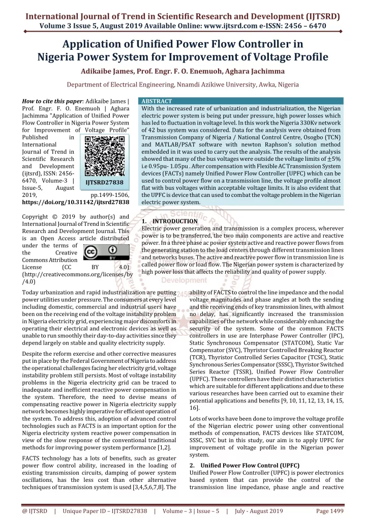
With the increased rate of urbanization and industrialization, the Nigerian electric power system is being put under pressure, high power losses which has led to fluctuation in voltage level. In this work the Nigeria 330Kv network of 42 bus system was considered. Data for the analysis were obtained from Transmission Company of Nigeria National Control Centre, Osogbo TCN and MATLAB PSAT software with newton Raphson's solution method embedded in it was used to carry out the analysis. The results of the analysis showed that many of the bus voltages were outside the voltage limits of u00c2u00b15 i.e 0.95pu 1.05pu . After compensation with Flexible AC Transmission System devices FACTs namely Unified Power Flow Controller UPFC which can be used to control power flow on a transmission line, the voltage profile almost flat with bus voltages within acceptable voltage limits. It is also evident that the UPFC is device that can used to combat the voltage problem in the Nigerian electric power system. Adikaibe James | Prof. Engr. F. O. Enemuoh | Aghara Jachimma "Application of Unified Power Flow Controller in Nigeria Power System for Improvement of Voltage Profile" Published in International Journal of Trend in Scientific Research and Development (ijtsrd), ISSN: 2456-6470, Volume-3 | Issue-5 , August 2019, URL: https://www.ijtsrd.com/papers/ijtsrd27838.pdf Paper URL: https://www.ijtsrd.com/engineering/electrical-engineering/27838/application-of-unified-power-flow-controller-in-nigeria-power-system-for-improvement-of-voltage-profile/adikaibe-james<br>

E N D
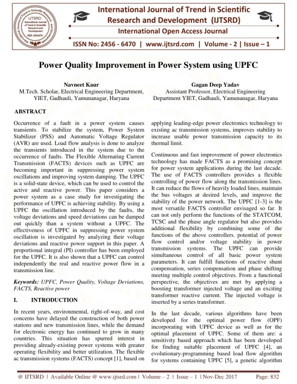
International Journal of Trend in Scientific Research and Development (IJTSRD) Volume 3 Issue 5, August 2019 Available Online: www.ijtsrd.com e-ISSN: 2456 – 6470 Application of Unified Power Flow Controller in Nigeria Power System for Improvement of Voltage Profile Adikaibe James, Prof. Engr. F. O. Enemuoh,Aghara Jachimma Department of Electrical Engineering, Nnamdi Azikiwe University, Awka, Nigeria How to cite this paper: Adikaibe James | Prof. Engr. F. O. Enemuoh | Aghara Jachimma "Application of Unified Power Flow Controller in Nigeria Power System for Improvement of Voltage Profile" Published in International Journal of Trend in Scientific Research and Development (ijtsrd), ISSN: 2456- 6470, Volume-3 | Issue-5, August 2019, https://doi.org/10.31142/ijtsrd27838 Copyright © 2019 by author(s) and International Journal of Trend in Scientific Research and Development Journal. This is an Open Access article distributed under the terms of the Creative Commons Attribution License (CC (http://creativecommons.org/licenses/by /4.0) Today urbanization and rapid industrialization are putting power utilities under pressure. The consumers at every level including domestic, commercial and industrial users have been on the receiving end of the voltage instability problem in Nigeria electricity grid, experiencing major discomforts in operating their electrical and electronic devices as well as unable to run smoothly their day-to-day activities since they depend largely on stable and quality electricity supply. Despite the reform exercise and other corrective measures put in place by the Federal Government of Nigeria to address the operational challenges facing her electricity grid, voltage instability problem still persists. Most of voltage instability problems in the Nigeria electricity grid can be traced to inadequate and inefficient reactive power compensation in the system. Therefore, the need to devise means of compensating reactive power in Nigeria electricity supply network becomes highly imperative for efficient operation of the system. To address this, adoption of advanced control technologies such as FACTS is an important option for the Nigeria electricity system reactive power compensation in view of the slow response of the conventional traditional methods for improving power system performance [1,2]. FACTS technology has a lots of benefits, such as greater power flow control ability, increased in the loading of existing transmission circuits, damping of power system oscillations, has the less cost than other alternative techniques of transmission system is used [3,4,5,6,7,8]. The ABSTRACT With the increased rate of urbanization and industrialization, the Nigerian electric power system is being put under pressure, high power losses which has led to fluctuation in voltage level. In this work the Nigeria 330Kv network of 42 bus system was considered. Data for the analysis were obtained from Transmission Company of Nigeria / National Control Centre, Osogbo (TCN) and MATLAB/PSAT software with newton Raphson’s solution method embedded in it was used to carry out the analysis. The results of the analysis showed that many of the bus voltages were outside the voltage limits of ±5% i.e 0.95pu- 1.05pu . After compensation with Flexible AC Transmission System devices (FACTs) namely Unified Power Flow Controller (UPFC) which can be used to control power flow on a transmission line, the voltage profile almost flat with bus voltages within acceptable voltage limits. It is also evident that the UPFC is device that can used to combat the voltage problem in the Nigerian electric power system. 1.INTRODUCTION Electric power generation and transmission is a complex process, wherever power is to be transferred, the two main components are active and reactive power. In a three phase ac power system active and reactive power flows from the generating station to the load centers through different transmission lines and networks buses. The active and reactive power flow in transmission line is called power flow or load flow. The Nigerian power system is characterized by high power loss that affects the reliability and quality of power supply. IJTSRD27838 pp.1499-1506, BY 4.0) ability of FACTS to control the line impedance and the nodal voltage magnitudes and phase angles at both the sending and the receiving ends of key transmission lines, with almost no delay, has significantly increased the transmission capabilities of the network while considerably enhancing the security of the system. Some of the common FACTS controllers in use are Interphase Power Controller (IPC), Static Synchronous Compensator (STATCOM), Static Var Compensator (SVC), Thyristor Controlled Breaking Reactor (TCR), Thyristor Controlled Series Capacitor (TCSC), Static Synchronous Series Compensator (SSSC), Thyristor Switched Series Reactor (TSSR), Unified Power Flow Controller (UPFC). These controllers have their distinct characteristics which are suitable for different applications and due to these various researches have been carried out to examine their potential applications and benefits [9, 10, 11, 12, 13, 14, 15, 16]. Lots of works have been done to improve the voltage profile of the Nigerian electric power using other conventional methods of compensation, FACTS devices like STATCOM, SSSC, SVC but in this study, our aim is to apply UPFC for improvement of voltage profile in the Nigerian power system. 2.Unified Power Flow Control (UPFC) Unified Power Flow Controller (UPFC) is power electronics based system that can provide the control of the transmission line impedance, phase angle and reactive @ IJTSRD | Unique Paper ID – IJTSRD27838 | Volume – 3 | Issue – 5 | July - August 2019 Page 1499
International Journal of Trend in Scientific Research and Development (IJTSRD) @ www.ijtsrd.com eISSN: 2456-6470 power. This versatility of the UPFC makes it a prime FACTS device that can provide many of the control functions required to solve a wide range of dynamic and steady state problems encountered in power systems. Combining the STATCOM and the SSSC into a single device with a common control system represents the third generation of FACTS known as Unified Power Flow Controller (UPFC). It has the unique ability to control real and reactive power flow independently. The basic operation principle diagram of the UPFC is shown in Figure 1, and has been described in open literature [17, 18, 19, 20, 21, 22]. The Unified Power Flow Controller (UPFC) made out of two Voltage Source Converters (VSCs), which are connected through a common DC link capacitor. From figure 1, the basic function of converter 1 is to supply or absorb the real power demanded by converter 2 at the common dc link. This dc link power is converted back to ac and coupled to the transmission line via a shunt-connected transformer. Converter 1 can also generate or absorb controllable reactive power, if it is desired, and there by it can provide independent shunt reactive compensation for the line. It is important to note that whereas there is a closed “direct” path for the real power negotiated by the action of series voltage injection through Inverters 1 and 2 back to the line, the corresponding reactive power exchanged is supplied or absorbed locally by converter 2 and therefore it does not flow through the line. Thus, converter 1 can be operated at a unity power factor or be controlled to have a reactive power exchange with the line independently of the reactive power exchanged by the by the converter 2. This means there is no continuous reactive power flow through UPFC. Figure2: Phasor diagram representation of modes of operation of UPFC A.Terminal Voltage Regulation regulation, similar to that obtainable with a transformer tap- changer having infinitely small steps. Where ???= ∆? is injected in phase or antiphase with ?. B.Line impedance compensation or Series capacitor compensation ???= ?? is in quadrature with the line current. C.Transmission angle regulation, (phase shifting) ???= ?? is injected with angular relationship with respect to ? that achieves the desired phase shift (advance or retard) without any change in magnitude. D.Simultaneous control of voltage, impedance, and angle Multifunction power flow control, executed by simultaneous terminal voltage regulation, series capacitive compensation, and phase shifting where ???= ∆? + ??+ ??. 3.Problem Formulation Due to the complexity that arises in solving the equations, since the functions for real and reactive powers are expressed in terms of non-linear algebraic equations. Iterative methods for solving equations shall be used in solving load flow problems as related to this work. A Newton-Raphson iterative technique was of load flow was used to simulate and investigate the power and voltage at each bus. A MATLAB/PSAT software was also used to run the simulation as it has the Newton-Raphson technique embedded in it. 3.1 Modelling of UPFC for Active and Reactive Power Evaluation Terminal voltage The modelling is carried out for the evaluation of the real and reactive power using the equivalent circuit of figure 3 Figure1: Implementation of the UPFC by back to back source converters. 2.1.Mode Of Operation Operation of the UPFC from the standpoint of conventional power transmission based on reactive shunt compensation, series compensation, and phase shifting, the UPFC can fulfill these functions and thereby meet multiple control objectives by adding the injected voltage ???, with appropriate amplitude and phase angle, to the terminal voltage ?. Using phasor representation, the basic UPFC power flow control functions are illustrated in Figure 2 Figure3. Equivalent circuit of a UPFC between two buses i and j The active and reactive powers of the series convertor (SSSC) are as follow. ???= ???+ ????= ????∗????? [?∗???∗?+ ?∗???∗? + Y???∗??]………(1) Expanding equation 1 and separating the real and imaginary points we have that ???= /???/????+ /???/ /??????cos(δ??− δ?? + − δ??)] +/V??//V?/[G???δ??− δ?? + B??sin?δ??− δ?? ] …(2) ?????/???/?/???/+/???//??/[???sin(???− ??) − ???cos(???− ??+/???//??/[???sin???−??+???cos???−??] ……. (3) ?????? (δ?? @ IJTSRD | Unique Paper ID – IJTSRD27838 | Volume – 3 | Issue – 5 | July - August 2019 Page 1500
International Journal of Trend in Scientific Research and Development (IJTSRD) @ www.ijtsrd.com eISSN: 2456-6470 Also, the active and reactive power of the shunt controller (STATCOM) are obtained as ???= ???+ ????= ?????? Expanding equation 4 and separating the real and imaginary parts we have ???= −/??ℎ/2??0+ /??ℎ/ /??/??0cos(δsh−δi+??0??? (δsh−δj)] ?????/???/?/???/+/???//??/[???sin(???− ??) − ???cos(???− ??)] Since we assume lossless converters, the UPFC neither aborts nor injects active power with respect to the AC system. Hence the constraint equation is ???+ ???= 0…………………………………………………………. (7) Where ???is the series converter real power flow ???is the Shunt converter real power flow ??? is the Series converter reactive power flow ??? is the Shunt converter reactive power flow ??? is the Injected series voltage source ??? is the Injected shut voltage source ??? is the Current flowing through the UPFC shut converter ??? is the self conductance of the shunt converter ??? is the self susceptance of the shunt converter δ?? is the Voltage angle of the injected series voltage source δ?? is the voltage angle of the injected shunt voltage source 3.2 Load Flow Analysis with Newton-Raphson Method Let Pi and Qi denote the net real andreactive power entering the network at bus i. Then the complex conjugate of the power injected at bus is given b S?= P?+ jQ?……………… (11) P?− jQ?= V?*∑ Y?? ??? V?= V?l*L Substituting equation 8 and 9 in 12 e have P?− jQ?∑ /Y?? ??? //V?/< θ??+ ??− ?? ………….…….(13) From the preceding equation we obtain the following form of the power-flow equations: P? =∑ |Y?? ??? V?V???? (???+ ??− ??) ?? =∑ |Y?? ??? V?V?|sin (???+ ??− ??) Where V? is the voltage at bus i V? is the voltage at bus j δ? is the voltage angle at bus i δ? is the voltage angle at bus j Expanding equation 13, we have ??− ???= ?????− ???????? ?δ?− δ?? − ????sin ?δ?− δ??????+ ??????? − ???????? ?δ?− δ?? + ?????sin ?δ?− δ??????? = ??????− ?????????? ?δ?− δ?? + ????[???????δ?− δ?? + ???????− ????????????δ?− δ?? + ???????????δ?− δ??…… (16) Separating the real and imaginary parts from both sending and receiving end we have that: For sending Bus ???= ??????− ????[?????? ?δ?− δ??+ B??sin ?δ?− δ??] ∗] ….. (4) ∗= −?????? ∗[??? ∗??? .......................... (12) ? ? ……. (5) ………………. (14) ? …. (6) ……………….. (15) ? Load flow studies are one of the most important aspects of power system planning and operation. The load flow gives us the sinusoidal steady state of the entire system - voltages, real and reactive power generated and absorbed and line losses. Newton-Raphson’s solution method was used to carry out the analysis because of its sparsity, fast convergence and simplicity attribute as compared to other solution methods. Consider the line diagram of a two bus system shown in figure 4 ……… (17) ???= −??????− ????[?????? ?δ?− δ?? − B??cos?δ?− δ??] ……… (18) Similarly, for the receiving bus ???= ??????− ????????cos?δ?− δ?? − B??cos?δ?− δ??? ………. (19) ???= −??????− ???????cos?δ?− δ?? − B??cos?δ?− δ??? ………. (20) The objective of the Newton-Raphson method is to produce values for |Vi| and δi that will match the prescribed Pdi and Qdi as determined from Equations (14) and (15). At each iteration of the method, new estimates of |Vi| and δi for the non-slack buses (i= 2, 3, … , N) are generated. At the end of each iteration, the power mismatch is given by ΔPi =Pi,sch - Pi, ………………………………………….......……(21) ΔQi=Qi,sch - Qi. ………………………………………..……...…..(22) The complex power flow equations for uncompensated transmission system in solved by Newton –Raphson’s iterative method are defined thus. ??= ??− ???= ∑ / δ?) i = 1,2..n ......(23) Figure4: Two bus system line diagram o transmission line The power-flow problem discusse in this section will be presented in terms of the ????Ybus matrix whose elements are of the form ???= ? ????e?θ??= ? ???????θ??+ ?? ????sin θ??= ???+ ????……. (8) For i, k = 1, 2, . . . , N. Let the voltae at bus I be denoted by ??= | ??|e?δ?= |??|????δ?+ ????δ?? For i= 1, 2, . . . , N The net current injected into the etwork at bus I in terms of the elements Yin of the ???? is determined by I?= Y??Y?+ Y??Y?+ …+ Y??Y?∑ .….. (9) ? ?????// ??//???/??? (θ??+ δ?− , i=1, 2…,n …….. (10) ? ??? Y?? @ IJTSRD | Unique Paper ID – IJTSRD27838 | Volume – 3 | Issue – 5 | July - August 2019 Page 1501
International Journal of Trend in Scientific Research and Development (IJTSRD) @ www.ijtsrd.com eISSN: 2456-6470 ? ?????// ??//???/??? (θ??+ δ?− ??? = element of the bus admittance matrix δ? = Voltage angle at bus i δ? = Voltage angle at nth Bus θ?? = Angle associated with ??? Then the new estimates for the bus voltages are ?? ??? The solution of equation enables us to identify weak points in the system where the voltages magnitude lies outside the voltage limits of ±5%. ??= ??− ???= ∑ δ?) i = 1,2,..n... (24) For compensated transmission system, equation 24 is modified and is defined by Q?= Q?− Q??+ Q??= − ∑ δ?− δ?) ........ (25) Where ?? = Real power generated at the ith bus ??= Reactive power generated at the ith Bus ??? = Real power consumed at the ith bus ?? = Voltage of the nth bus. ??? = Reactive power consumed at the ith bus ?? = Voltage at bus i / ? ???V?//??//Y??/??? (θ??+ / (???)= ?? (?)+ ∆?? (?)………………………………...………..........(26) (?)? + ∆|?? (?)|……………………………………..... (27) ???? = ??? 3.3. Modelling load Flow Equations with UPFC The linearized system of power flow equations for UPFC in connection with the rest of the network in obtained using Newton- Raphson power flow equation given by [F (x)] = [J] [ΔX] .................. (28) Where F (x) is the Power and control mismatch vectors Δx is the Incremental vector of state variables Where ΔX is the solution vector and it is given by ΔX= Δδ? [FX] = ΔP? Δδ? ΔP? Δ/V?? Δ Q? Δ/V?/ ΔQ? ....... 29 ....... 30 Δ δ?? ΔP?? ΔV?? ΔQ?? Δδ?? ΔP J is the matrix of partial derivative of F(x) with respect to x, Let us assume the UPFC is connected to node i and the power and the power system is connected to node j. UPFC is required to control voltage magnitude of node i and active power low from node j to node i. Reactive power is infected at node j. Here we can re-write equation 28 as ∂P? ∂P? ∂P? ∂δ?∂δ?∂/V??/ ∂P?∂P? ∂δ?∂δ?∂/V?/ ∂Q? ∂Q? ∂Q? ∂δ?∂δ?∂/V??/∂/V?∂δ?? ∂P? ∂P? ∂P? ∂/V?/ ∂δ??∂/V??/ ∂P? ∂δ?? ∆δ? 0 ∂P? ∂P? ∂δ?? ∂/V??/ 0 ∂P? ∆?? ∆δ? ∆?? ∂Q? ∂Q? ∂Q? ∂/V??/ ∂δ?? ∂Q? ∆/V??/ ∆?? = .…. 31 ∆/V? ∂Q? ∂Q? 0 ∂δ?∂δ? ∂Q?∂Q? ∂/V?/∂δ?? ∂Q? ∂/V??/ 0 ∆?? ∆ δ?? ∂P?? ∂P?? 0 ∂δ? ∂δ? ∂Q??∂Q?? 0 ∂δ?∂δ? ∆??? ∂P?? ∂/V?/∂δ?? 0 ∂P?? ∂P?? ∂/V??/ ∆/V??/ ∆??? ∆ δ?? ∂Q?? ∂/V?/∂δ?? ∂Q?? ∂Q?? ∂/V??/ 0 ∂sh ∆P ∂P∂P ∂P∂P ∂δ?∂δ? ∂/V?/ ∂δ?? ∂P ∂/V??/∂δ?? ∂δ?? ∂P ∂P @ IJTSRD | Unique Paper ID – IJTSRD27838 | Volume – 3 | Issue – 5 | July - August 2019 Page 1502
International Journal of Trend in Scientific Research and Development (IJTSRD) @ www.ijtsrd.com eISSN: 2456-6470 4.SIMULATION AND RESULT ANALYSIS Overview of Nigeria 330kV Transmission Network used for the case study The input data for the power flow analysis include the bus data that is real and reactive powers of the generator buses, transmission line data (impedance of lines), voltages and transformer/load data obtained from Power Holding Company of Nigeria (PHCN) are as presented in Tables contained in the appendix. They are used to carry out the analysis. The single-line diagram of the existing 330kV Nigeria transmission network used as the case study is as shown in Figure 5. It has 42 buses with nine generating station. The Egbin power station was chosen as the slack bus because it has the highest generating capacity of 1320MW. 4.1 SIMULATION STEPS MATLAB/PSAT software was used to simulate the proposed model. The model of simulation of the proposes model using the developed MATLAB code are as follows. The algorithm is represented in figure 4 Run load flow on the proposed model before and after incorporation with UPFC. Plot the graph of voltages (p.u) against the buses. Compare the result in graph. Figure4: Flow Chart for the Analysis of UPFC Compensation Algorithm. Figure5: Modelled Nigerian 330kV power system on PSAT @ IJTSRD | Unique Paper ID – IJTSRD27838 | Volume – 3 | Issue – 5 | July - August 2019 Page 1503
International Journal of Trend in Scientific Research and Development (IJTSRD) @ www.ijtsrd.com eISSN: 2456-6470 5.RESULTS Load flow analysis was carried out on the network to investigate the buses outside voltage limits and also losses along the lines. Results of the simulations are in figures 5, 6, 7 and table 1. Table1: Bus voltages and angles with and without UPFC Bus Number without UPFC Bus1 B. Kebbi 0.92327917 Bus10 Ganmo 0.993467034 Bus11 Mando 0.936016761 Bus12 Katampe 0.96932409 Bus13 Gwagwalada 0.972349829 Bus14 Olorunsogo 1 Bus15 Akangba 0.967384227 Bus16 Egbin 1.012 Bus17 Omotosho 1 Bus18 Oke-Aro 0.980006451 Bus19 Benin 1.01126355 Bus2 Kainji 1 Bus20 Kano 0.912025045 Bus21 Jos 0.876609365 Bus22 Lokoja 0.967875943 Bus23 Aja 1.00915049 Bus24 Onitsha 0.989343263 Bus25 Ajaokuta 0.97281235 Bus26 Delta 1.012 Bus27 Sapele 1.012 Bus28 Makurdi 0.893989619 Bus29 Gombe 0.812150442 Bus3 Jebba 0.999264259 Bus30 New Haven 0.916384533 Bus31 Okpai 1.012 Bus32 Alaoji 1 Bus33 Geregu 1 Bus34 Aladji 1.007415339 Bus35 Ugwuaji 0.914546079 Bus36 Yola 0.801049641 Bus37 Damaturu 0.804956113 Bus38 Afam 1.003 Bus39 IkotEkpene 0.980610751 Bus4 Jebba GS 1 Bus40 Adiabor 0.986716932 Bus41 Odukpani 0.991 Bus42 Sakete 0.954470925 Bus5 Shiroro 1 Bus6 Osogbo 0.996650962 Bus7 Aeyede 0.972034158 Bus8 Ikeja West 0.973856683 Bus9 Ihovbor 1 Voltage (p.u) Voltage (p.u) with UPFC 0.98177 0.99455 0.989 0.97002 0.9732 1 0.98276 1.012 1 1 1.0143 1 0.98415 0.98555 0.96994 1.0092 1.0043 0.97499 1.012 1.012 0.98314 0.99 0.99943 0.98 1.012 1 1 1.0074 0.97883 0.98458 0.9833 1.003 0.9889 1 0.98844 0.991 0.97019 1 0.99881 0.97309 0.98913 1 Voltage angle without UPFC -0.26392 -0.13674 -0.40837 -0.30952 -0.29775 -0.09085 -0.10562 0 -0.0174 -0.07579 -0.01387 -0.10788 -0.42084 -0.47534 -0.21473 -0.00437 0.006314 -0.18027 0.009153 0.000476 -0.29127 -0.71929 -0.13043 -0.10314 0.044018 0.172816 -0.1154 -0.00267 -0.10913 -0.75828 -0.75371 0.196087 0.145729 -0.12617 0.19726 0.214988 -0.13171 -0.27781 -0.11878 -0.12932 -0.09482 0.049304 Voltage angle with UPFC -0.12408 -0.12508 -0.37615 -0.28767 -0.27645 -0.08538 -0.10388 0 -0.01423 -0.07584 -0.01021 -0.09377 -0.3865 -0.42692 -0.1999 -0.00437 0.005664 -0.16727 0.013138 0.004477 -0.26873 -0.61011 -0.11731 -0.10298 0.044556 0.168112 -0.10237 0.00132 -0.1066 -0.63654 -0.62535 0.191143 0.139584 -0.11303 0.191375 0.209277 -0.12916 -0.25354 -0.109 -0.12185 -0.09342 .056249 Bus Name 1.2 WITHOUT UPFC WITH UPFC 1 0.8 PU VOLTS 0.6 0.4 0.2 0 Figure6: Bar plot of bus voltage with and without UPFC @ IJTSRD | Unique Paper ID – IJTSRD27838 | Volume – 3 | Issue – 5 | July - August 2019 Page 1504
International Journal of Trend in Scientific Research and Development (IJTSRD) @ www.ijtsrd.com eISSN: 2456-6470 6.DISCUSSION The analysis of Nigeria 330kV 42 bus network using Newton- Raphson’s power flow solution algorithm with MATLAB/PSAT software was successfully completed. The results obtained revealed the weak buses with values outside the statutory limit of 0.95p.u. (313.5kV) and 1.05p.u. (346.kV). Four (4) UPFC devices where placed at some weak buses in the network namely Birnin Kebbi, Kano, New haven and Gombe which resulted to almost a flat voltage profile with all the buses within voltage limits as in figure 6. The bar plot in the figure 6, shows the comparism of the bus voltages before and after compensation by UPFC while figure 7 is the corresponding voltage angle of the bus voltages before and after compensation. The voltage profile of the system was improved as a result of the series compensation voltages added to the system with controllable magnitude by the UPFC. 7.CONCLUSION The Nigerian 330kV transmission system associated with various challenges like instability of the system as a result of voltage profile violation, transmission line inefficiency, problem of long transmission lines, network being stretched beyond thermal limit, and poor power quality that causes constant power failure in Nigeria power system were discussed. Newton-Raphson’s solution method because of its sparsity, fast convergence and simplicity attributes compared to other solution methods was chosen. UPFC was used because of its ability control the network parameters which are voltage magnitude, phase angle and impedance simultaneously and independently. In the simulation study MATLAB/PSAT simulation tool was used for the analysis. The result of the simulation of the uncompensated and compensated network were recorded in table 1. It was found that the UPFC improved the voltages at the bus of the power system. 8.REFERENCES [1]Jokojeje, R.A., Adejumobi, I.A., Adebisi, O.I., Mufutau, W.O. (2015) Reactive Power Compensation in Nigeria Electricity Grid Using Static Synchronous Compensator (STATCOM). IOSR Journal of Electrical and Electronics Engineering (IOSR-JEEE) e-ISSN: 2278-1676, p-ISSN: 2320-3331, Volume 10, Issue 2 Ver. IV(Mar – Apr. 2015), PP 08-20 [2]E. Lerch, D. Povh, R. Witzmann, R. Hlebcar, and R. Mihalic, (1994) Simulation and Performance Analysis of Unified Power Flow Controller, Conseil International des Grands Re´seaux Electriques, Paris, 1994, paper 14-205. [3]Gabriela Glanzmann, (2005), Facts Alternating Current Transmission System. EEH-Power System Laboratory ETH, Zurich. [4]K. R. Padiyar (2007) FACTS Controllers in Power Transmission and Distribution. New Age International Publishers, 2007. [5]N.G Hingorani and L. Gyugi, (2000) Understanding FACTS Concepts and Technology of Flexible AC Transmission Systems. IEEE press, New York, 2000. [6] L. Gyugi, C.D. Schandra, S. L Williams T. R. Rietman, D. R. Torgerson, and A Edris, (1995). The Unified Power Flow Controlling a New Approach to Power Transmission Control. IEEE trans power Delivery, Vol. 10, No. 2 (1995) pp. 1085-1093 [7]L. Gyugi, (1992). A Unified Power Control Concept of Flexible AC Transmission System. IEEE proceeding –C, vol. 139. Nos. 4, (1992), pp 323-331. [8]Raju Pandey, A. K. Kori (2012) Real and Reactive Power Flow Control Using Flexible Ac Transmission System @ IJTSRD | Unique Paper ID – IJTSRD27838 | Volume – 3 | Issue – 5 | July - August 2019 Page 1505
International Journal of Trend in Scientific Research and Development (IJTSRD) @ www.ijtsrd.com eISSN: 2456-6470 Connected to a Transmission Line: A Power Injection Concept. International Journal of Advanced Research in Computer Engineering & Technology (IJARCET) Volume 1, Issue 6, August 2012, pp. 252-256. [16]T. Nguyen and C.T. Vu (2006). Complex-Variable Newton-Raphson Load- Flow Analysis with FACTS Devices. in IEEE Transmission and Distribution Conference and Exhibition, 2006, pp. 183 – 190. [9]B. Singh, N. K. Sharma and A. N. Tiwari (2010). A Comprehensive Survey of Coordinated Control Techniques of FACTS Controllers in Multi Machine Power System Environments. International Journal of Engineering Science and Technology, 2 (6), pp. 1507 – 1525. [17]Rietman T. R., Edris A. A., Schauder C. D, Torgerson D. R., Williams S.L. (1995). The Unified Power Flow Controller: A New Approach to Power Transmission Control. IEEE Trans on Power Delivery, Vol. IO, No.2, pp.1085-1093, April 1995. [18]Keri A. J. F., Lombard X, Edris A. A, Mehraban A. S., Elate A., (1999) UPFC: Modeling and Analysis. IEEE Trans on Power Delivery, Vol. 14, No2, pp.648-654, April 1999. [10]K. R. Padiyar, (2007) FACTS Controllers in Power Transmission and Distribution. New Age International Publishers, 2007. [19]Lambord X. and Thernond P.G. (1997) Control of Unified Power Flow Controller: Comparison of Methods on the Basis of a Detailed Numerical Model. IEEE Trans. on Power Systems Vol. 12, No. 2, May 1997, pp.824-830. [11]A. K. Mohanty and A. K. Barik (2013) Power System Stability Improvement International Journal of Modern Engineering Research (IJMER), vol. 1, no. 2, 2013, pp. 666-672. Using FACTS Devices. [12]Manoj Nair (2010) EHV Ac & Dc Transmission, in EHV Ac & Dc Transmission.2nd ed. Bhopal, India Balaji Learning Books, 2010, pp. 161-162. [20]Manzar Rahman, Mohammed Ahmad, R. Gutman, R.J. O’ Keefe, Robert J. Nelson, Jianhua Bian, (1997) “UPFC Application on the AEP System ”IEEET rans. on Power Systems, Vol. 12, No 4,1997. [13]S. Jamhoria and L. Srivastava (2014). Applications of Thyristor Controlled Series. International Conference on Power, Signals, Controls and Computation (EPSCICON), 2014. [21]Nabavt Niaki and Iravani, MR., (1996) Steady State and Dynamic models of Unified Power Flow Controller for Power System Studies. IEEE Transactions on Power System ~01.11N, o. 4, pp. 1937-1941N ov.1996. [14]Z. Muller, J. Svec and J. Tlusty J. E. Essilfie (2014) STATCOM Effect on Voltage Stability in Ghanaian Electrical Grid.in 15th Conference on Electric Power Engineering (EPE), Proceedings of the 2014, Brno, 12-14 May, 2014, pp. 235 – 240. [22]Noroozian M. Angquist L., Ghandhari M. and Andersson G. (1997) of UPFC for Optimal Power Flow Control. IEEE Transactions on Power Delivery, vol. 12, No. 4, pp.1629-1634, October 1997. International Scientific [23]Sunil Kumar Jilledi, Shalini J., Birtukan Teshome (2015). Implementing of UPFC in the Power System Network to Control Power Flow and Minimization of Losses. American Journal of Energy and Power Engineering. Vol. 2, No. 2, 2015, pp. 12-19. [15]S. S. Rangarajan, M. Ambili, P. Sujyothi and V. G. Nithya S. Sreejith (2014), Enhancing The Power Transfer Capability in a Power System Network Using Series Connected Facts Devices for Increased Renewable Penetration, in International Conference on Advances in Electrical Engineering (ICAEE), Vellore, Jan. 2014, pp. 1 – 6. @ IJTSRD | Unique Paper ID – IJTSRD27838 | Volume – 3 | Issue – 5 | July - August 2019 Page 1506