Download
1 / 6
60 likes | 69 Views
Occurrence of a fault in a power system causes transients. To stabilize the system, Power System Stabilizer PSS and Automatic Voltage Regulator AVR are used. Load flow analysis is done to analyze the transients introduced in the system due to the occurrence of faults. The Flexible Alternating Current Transmission FACTS devices such as UPFC are becoming important in suppressing power system oscillations and improving system damping. The UPFC is a solid state device, which can be used to control the active and reactive power. This paper considers a power system as a case study for investigating the performance of UPFC is achieving stability. By using a UPFC the oscillation introduced by the faults, the voltage deviations and speed deviations can be damped out quickly than a system without a UPFC. The effectiveness of UPFC in suppressing power system oscillation is investigated by analyzing their voltage deviations and reactive power support in this paper. A proportional integral PI controller has been employed for the UPFC. It is also shown that a UPFC can control independently the real and reactive power flow in a transmission line. Navneet Kaur | Gagan Deep Yadav "Power Quality Improvement in Power System using UPFC" Published in International Journal of Trend in Scientific Research and Development (ijtsrd), ISSN: 2456-6470, Volume-2 | Issue-1 , December 2017, URL: https://www.ijtsrd.com/papers/ijtsrd7139.pdf Paper URL: http://www.ijtsrd.com/engineering/electrical-engineering/7139/power-quality-improvement-in-power-system-using-upfc/navneet-kaur<br>

E N D
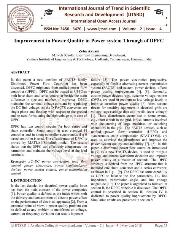
International Journal of Trend in Scientific Research and Development (IJTSRD) International Open Access Journal ISSN No: 2456 - 6470 | www.ijtsrd.com | Volume - 2 | Issue – 1 Power Quality Improvement in Power System using UPFC Navneet Kaur Gagan Deep Yadav M.Tech. Scholar, Electrical Engineering Department, YIET, Gadhauli, Yamunanagar, Haryana Assistant Professor, Electrical Engineering Department YIET, Gadhauli, Yamunanagar, Haryana ABSTRACT Occurrence of a fault in a power system causes transients. To stabilize the system, Power System Stabilizer (PSS) and Automatic Voltage Regulator (AVR) are used. Load flow analysis is done to analyze the transients introduced in the system due to the occurrence of faults. The Flexible Alternating Current Transmission (FACTS) devices such as UPFC are becoming important in suppressing power system oscillations and improving system damping. The UPFC is a solid-state device, which can be used to control the active and reactive power. This paper considers a power system as a case study for investigating the performance of UPFC is achieving stability. By using a UPFC the oscillation introduced by the faults, the voltage deviations and speed deviations can be damped out quickly than a system without a UPFC. The effectiveness of UPFC in suppressing power system oscillation is investigated by analyzing their voltage deviations and reactive power support in this paper. A proportional integral (PI) controller has been employed for the UPFC. It is also shown that a UPFC can control independently the real and reactive power flow in a transmission line. applying leading-edge power electronics technology to existing ac transmission systems, improves stability to increase usable power transmission capacity to its thermal limit. Continuous and fast improvement of power electronics technology has made FACTS as a promising concept for power system applications during the last decade. The use of FACTS controllers provides a flexible controlling of power flow along the transmission lines. It can reduce the flows of heavily loaded lines, maintain the bus voltages at desired levels, and improve the stability of the power network. The UPFC [1-3] is the most versatile FACTS controller envisaged so far. It can not only perform the functions of the STATCOM, TCSC and the phase angle regulator but also provides additional flexibility by combining some of the functions of the above controllers. potential of power flow control and/or voltage stability in power transmission systems. The UPFC can provide simultaneous control of all basic power system parameters. It can fulfill functions of reactive shunt compensation, series compensation and phase shifting meeting multiple control objectives. From a functional perspective, the objectives are met by applying a boosting transformer injected voltage and an exciting transformer reactive current. The injected voltage is inserted by a series transformer. Keywords: UPFC, Power Quality, Voltage Deviations, FACTS, Reactive power I. INTRODUCTION In recent years, environmental, right-of-way, and cost concerns have delayed the construction of both power stations and new transmission lines, while the demand for electronic energy has continued to grow in many countries. This situation has spurred interest in providing already-existing power systems with greater operating flexibility and better utilization. The flexible ac transmission systems (FACTS) concept [1], based on In the last decade, various algorithms have been developed for the optimal power flow (OPF) incorporating with UPFC device as well as for the optimal placement of UPFC. Some of them are: a sensitivity based approach which has been developed for finding suitable placement of UPFC [4], an evolutionary-programming based load flow algorithm for systems containing UPFC [5], a genetic algorithm @ IJTSRD | Available Online @ www.ijtsrd.com | Volume – 2 | Issue – 1 | Nov-Dec 2017 Page: 832
(GA) which proposed for solving the optimal location problem of UPFC [6], particle swarm optimization (PSO) for optimal location of FACTS devices [7], etc. Ara et al. [8] proposed a solution procedure using nonlinear programming (NLP) and mixed-integer nonlinear programming (MINLP) for solving the optimal location and setting of FACTS incorporated in the optimal power-flow problem with the objective functions being considered are the total fuel cost, power losses, and system load ability with and without FACTS installation and improving the power system operation. Sawhney and Jeyasurya [9] presented the application of UPFC to improve the transfer capability of a power system to meet some of the challenges of power system operation caused by deregulation in the electric power industry and opening of the market for delivery of cheaper energy to the customers. Alomoush [10] developed a mathematical approach allocating the contributions of UPFCs to transmission system usage by making use of a dc-based load flow model of UPFC- inserted transmission lines based on a previously derived dc-based injection model of UPFC-embedded lines. Relationships were derived to model the impact of UPFC on line flows and transmission usage by using modified admittances and distribution factors that model impact of utilizing UPFC on line flows and system usage. Taher and Amooshahi [11] presented the application of hybrid immune algorithm (HIA) such as immune GA (IGA) and immune PSO (IPSO) to find optimal location of UPFC to achieve optimal performance of power system. Simulations were performed on IEEE 14-bus and IEEE 30-bus test systems considering the overall cost function as the objective function, including the total active and reactive production cost function of the generators and installation cost of UPFCs. Shaheen et al. [12] presented a new approach based on differential evolution (DE) technique to find out the optimal placement and parameter setting of UPFC for enhancing power system security under single line contingencies. Vural and Tümay [13] focused on the mathematical modeling implementation of the device in conventional Newton– Raphson (NR) power flow algorithm and in power system analysis software package (PSASP). Visakha et al. [14] presented an approach for selecting suitable locations of UPFC considering normal and network contingencies after evaluating the degree of severity of the contingencies.. Roy et al. proposed biogeography based optimization (BBO) [15] to solve TCSC and TCPS based optimal reactive power dispatch (ORPD) problem for minimizing voltage deviation and transmission loss of IEEE 30-bus test system. Panda International Journal of Trend in Scientific Research and Development (IJTSRD) ISSN: 2456-6470 [16] investigated the application of non-dominated sorting in genetic algorithms-II (NSGA-II) technique for designing a FACTS based controller to improve the stability of the power system with minimum control effort. The proposed technique was applied for generating a Pareto set of global optimal solutions to the multi objective optimization problem. Furthermore, the best compromise solution from the obtained Pareto solution set was chosen by using a fuzzy-based membership value assignment method. Edward et al. [17] developed an enhanced bacterial foraging algorithm (EBFA) by including Nelder–Mead (NM) algorithm to conventional bacterial foraging algorithm (BFA) for better performance of power system. This was done to overcome the difficulty of optimal parameter selection of the conventional BFA technique. Hassan et al. proposed GA [18] technique for the stabilization of power systems using UPFC devices. Om Krishan et al. [19] presented a pitch angle control technique to enhance the power quality of wind-diesel based power system. II. Operation and Modelling of UPFC The Unified Power Flow Controller (UPFC) was proposed first time for real turn-off time control and dynamic compensation of ac transmission systems. The Unified Power Flow Controller is consists of two switching converters, which are considered as voltage sourced inverters using gate thyristor valves. These inverters, labeled "VSC1” and "VSC2" in the figure are operated with a common dc link provided by a dc storage capacitor. With this arrangement the ac power converter in which the real power can freely flow in either direction between the ac terminals of the two inverters and each inverter can independently generate as well as absorb the reactive power at its own ac output terminal. Since the series converter of the UPFC can inject a voltage with variable magnitude and phase angle it can exchange real power with the transmission line with the help of series transformer. However a UPFC as a whole (both converter) cannot supply or absorb real power in steady state (except for the power drawn to compensate for the losses).Unless it has a power source at DC terminals. Thus the shunt branch is required for compensate (from the system for any real power drawn/supplied by the series branch and the losses. when the power balance is not maintained, at that situation the capacitor cannot remain at a constant voltage. Shunt branch also can independently exchange reactive power with the system. of UPFC for the @ IJTSRD | Available Online @ www.ijtsrd.com | Volume – 2 | Issue – 1 | Nov-Dec 2017 Page: 833
International Journal of Trend in Scientific Research and Development (IJTSRD) ISSN: 2456-6470 voltage V0 Using phasor representation, the basic UPFC power flow control functions are illustrated in Fig.2. A.Basic Principle of P & Q Control Consider Fig.3. At a simple two machine (or two bus ac inertia) system with sending end voltage Vs, receiving- end voltage Vr, and line (or tie) impedance X (assumed, for simplicity, inductive) is shown. At Fig. 3.3 the voltages of the system in form of a phasor diagram are shown with transmission angle δ and │Vs│=│Vr│=│V│. Transmitted Fig: 1 The Schematic diagram of UPFC VSC 2 provides the main function of the UPFC by injecting a voltage Vpq with controllable magnitude Vpq (0≤ Vpq≤ Vpq max) and phase angle ρ (0≤ρ ≤ 360°), at the power frequency, insert with line via an insertion transformer. This injected voltage considered as synchronous ac voltage source. The transmission line current flows through this voltage source resulting in real and reactive power exchange between it and the ac system. Real power exchanged at the ac terminal (i.e., at the terminal of the insertion transformer) and the inverter help to convert the ac power into dc power, after that the dc power appears at the dc link as positive or negative real power demand. Reactive power exchanged at the ac terminal is generated internally by the inverter. The function of converter1 is to supply or absorb the real power demanded by converter 2 at the common dc link. The power of the dc link is converted back to ac and coupled to the transmission line via a shunt-connected transformer. If reactive power is required then VSC 1 can also generate or absorb controllable reactive power, so it can provide independent shunt reactive compensation for the line. It is also important to note that whereas there is a closed "direct" path for the real power negotiated by the action of series voltage injection through Inverters 1 and 2 back to the line, corresponding the reactive power exchanged is supplied or absorbed locally by Inverter 2 and therefore the reactive power does not flow through the line. So the Inverter 1 can be operated at a unity power factor or be controlled to have a reactive power exchange with the line independently of the reactive power exchanged by Inverter 2. That means there is no continuous reactive power flow through the UPFC. The Unified Power Flow Controller from the stand point of conventional power transmission based on reactive series compensation, shunt compensation, and phase shifting, the UPFC is the only device which can fulfill all these functions and thereby meet multiple control objectives by adding the injected voltage Vpq, with appropriate amplitude and phase angle, to the terminal 2 V ( sin P P X Power P= and the reactive power Q =Qs= 2 V 1 cos ( Q Q r X supplied at the ends of the line are shown plotted against angle δ. Fig 2 Basic UPFC control function. (a)Voltage Regulation (b) Series compensation. Fig 3 Simple two machine system.. It can be readily observed in Fig. 3 that the transmission line sees Vs + Vpq as the effective sending-end voltage. Thus, it is clear that the UPFC affects the voltage (both its magnitude and angle) across the transmission line and therefore it is reasonable to expect that it is able to control, by varying the magnitude and angle of Vpq the transmittable real power as well as the reactive power demand of the line at any given transmission angle @ IJTSRD | Available Online @ www.ijtsrd.com | Volume – 2 | Issue – 1 | Nov-Dec 2017 Page: 834
between the sending-end and receiving end voltages. International Journal of Trend in Scientific Research and Development (IJTSRD) ISSN: 2456-6470 to 3 second interval) 2≤t<3 Case 3: Line is restored. 3>t V V V V (1) pq q Considering the above cases the behavior of the line is being examined as follows. 2 2 1 1 Q Q P (2) 0 r ro A.System Performance without UPFC ➢System Voltage When Vpq=0 then * V V s r P jQ V r r jX (3) This is the main parameter to be controlled; the system voltage should have minimum variations when any fault occurs. When no compensation device is used to the system voltage drop down to a significant value as shown in Fig. 4. The heavy drop in voltage causes underperformance of the various equipments and components connected to the same system. In this case there is almost 45% voltage drop occurs, so the performance is not satisfactory. When Vpq≠0 then * V V V V r pq s r P jQ V r r jX jX (4) Subsituting j 2 cos sin s V Ve V 2 2 (5) j 2 cos sin r V Ve V 2 2 (6) And Fig.4: System voltage (rms) without UPFC. j 2 cos sin V V e V pq pq pq 2 2 (7) ➢Reactive Power Compensation The following expressions are obtained for P and Qr The system voltage depends upon the reactive power. If the system voltage drops, the reactive power should be injected in to the system and vice versa. But in this case as no compensation is used there is no injection of the reactive power and system further draws more reactive power support to compensate the losses which further worsen the condition. Fig. 4 shows the variation in the reactive power when the fault occurs in the time duration 2-3 sec. The increased value of the reactive power during fault interval shows that the system is drawing more reactive power to compensate its losses instead of delivering the reactive power. 2 V V pq X , sin cos2 P P P o pq X (8) 2 V V pq X 1 cos , sin2 Q Q Q r ro pq X (9) III. Simulations and Results To assess the UPFC’s capabilities through simulation software tool is needed. MATLAB/Simulink is being used for the simulation purpose in this work. A UPFC module that consists of three components: a steady state model, a dynamic model with its basic controllers. In this chapter, the analysis is done of power system when UPFC is connected to the system and when not connected. In the above system various cases are there; Case 1: Pre Fault condition 0<t≤2 Fig.4: Reactive power support during fault. Case 2: During Fault condition (Fault occurred during 2 @ IJTSRD | Available Online @ www.ijtsrd.com | Volume – 2 | Issue – 1 | Nov-Dec 2017 Page: 835
International Journal of Trend in Scientific Research and Development (IJTSRD) ISSN: 2456-6470 Fig 5: Three phase instantaneous voltage Fig 6: System voltage when UPFC is connected Fig. 5 shows the instantaneous three phase voltage when the fault occurs during time interval 2-3 sec. The zoomed view is also shown in order to show the difference in voltage of the three phases. All the phases has some drop but within the phases there is different voltage level. This cause imbalance in the three phase voltage although the fault is balanced type. Fig 7: Reactive power support by UPFC B.System Performance with UPFC ➢System Voltage CONCLUSIONS The proposed technique of adding the UPFC in the transmission line of the power system we get better results as compared to the older techniques power system stabilizer and automatic voltage controller in terms of damping out the transients quickly. We have carried out extensive computer simulations for studying the addition of both series compensation and shunt compensation given by the series controller and the shunt controller. From comparative study of the relative variation reactive power support, terminal voltage and active power. We have seen that the transient stability is enhanced by the use of UPFC. By using a UPFC we obtain better transient stability performance than the case without a UPFC. The system voltage is maintained within prescribed limits when UPFC is connected to the power system. Fig. 6 shows the system voltage variations when three phase fault occurs. From the figure, it can be clearly seen that the intensity of the fault is reduced when UPFC is connected to the system. The current drawn by the system is also reduced and system can be protected from over-heating of the system. The system voltage now drops to 25% of the normal value, which is almost half of the previous case when UPFC is not connected. The simulation is done for the severest of the faults i.e. three phase fault. This implies that UPFC can maintain the terminal conditions when critical condition arises. REFERENCES ➢Reactive Power Support 1.L. Gyugyi, “Unified power-flow control concept for flexible ac transmission systems,” Proc. Inst. Elect. Eng., vol. 139, pt. C, pp. 323–331, July 1992. 2.T. Ooi, S. Z. Dai, and X. Wang, “Solid-state series capacitive reactance compensators,” IEEE Trans. Power Delivery, vol. 7, no. 2, pp. 914–919, 1990. 3.S. Rigby and R. G. Harley, “An improved control scheme for a series compensator based on a voltage source inverter,” in IEEE/IAS Annu. Meeting, 1996, pp. 870–877. 4.Singh SN, Erlich I. “Locating unified power flow controller for enhancing power system loadability”. In: International conference on future power system; 2005. p. 1–5. 5.Wang KP, Yurevich J, Li A. Evolutionary- programming-based load flow algorithm for As mentioned above, if the system voltage drops to a certain value, the reactive power has to be injected to boost up the voltage. UPFC is like a reactive power storage medium. It deliverers the reactive power in to the power system when voltage drops due to any disturbance like fault etc. Fig. 7 shows the waveform for the reactive power. From the figure, it can be seen that there is decrease in reactive power, which signifies that reactive power is being injected to the system as compared to the previous case when there was increase in the reactive power. capacitive reactance @ IJTSRD | Available Online @ www.ijtsrd.com | Volume – 2 | Issue – 1 | Nov-Dec 2017 Page: 836
International Journal of Trend in Scientific Research and Development (IJTSRD) ISSN: 2456-6470 13.Vural AM, Tümay M. Mathematical modeling and analysis of a unified power flow controller: a comparison of two approaches in power flow studies and effects of UPFC location. Int J Electr Power Energy Syst 2007;29:617–29. 14.Visakha K, Thukaram D, Jenkins L. Application of UPFC for system security improvement under normal and network contingencies. Int J Electr Power Syst Res 2004;70:46–55. 15.Roy PK, Ghoshal SP, Thakur SS. Optimal reactive power dispatch considering FACTS devices using biogeography based optimization. Electr Power Compon Syst 2011;39(8):733–50. 16.Panda S. Application of non-dominated sorting genetic algorithm-II technique for optimal FACTS- based controller design. 2010;347:1047–64. 17.Edward JB, Rajasekar N, Sathiyasekar K, Senthilnathan N, Sarjila R. An enhanced bacterial foraging algorithm approach for optimal power flow problem including considering system 2013;52:622–8. 18.Hassan LH, Moghavvemi M, Almurib HAF, Steinmayer O. Application of genetic algorithm in optimization of unified power flow controller parameters and its location in the power system network. Int J Electr Power Energy Syst 2013;46:89–97. 19.Om Krishan, Sathans (2016), Frequency regulation in a standalone wind-diesel hybrid power system using pitch-angle controller. 3rd International Conference on Computing for Sustainable Global Development (INDIACom). systems containing unified power flow controllers. IEE Proc Gener Transm Distrib 2003;150:441–6. 6.Arabkhaburi D, Kazemi A, Yari M, Aghaei J. Optimal placement of UPFC in power systems using genetic algorithm. In: IEEE international conference on industrial technology; 2006. p. 1694– 9. 7.Saravanan M, Slochanal SMR, Venkatesh P, Abraham PS. Application of PSO technique for optimal location of FACST devices considering system loadability and cost of installation. Power Eng Conf 2005:716–21. 8.Lashkar Ara A, Kazemi A, Nabavi Niaki SA. Multiobjective optimal location of FACTS shunt- series controllers for power system operation planning. IEEE Trans Power Deliv 2012;27(2). 9.Sawhney H, Jeyasurya B. Application of unified power flow controller for available transfer capability enhancement. Int J Electr Power Sys Res 2004;69:155–60. 10.Alomoush Muwaffaq I. Impacts of UPFC on line flows and transmission usage. Int J Electr Power Sys Res 2004;71:223–34. 11.Taher SA, Amooshahi MK. New approach for optimal UPFC placement using hybrid immune algorithm in electric power systems. Int J Electr Power Energy Syst 2012;43:899–909. 12.Shaheen Husam I, Rashed Ghamgeen I, Cheng SJ. Optimal location and parameter setting of UPFC for enhancing power system security based on Differential Evolution algorithm. Int J Electr Power Energy Syst 2011;33:94–105. J Franklin Inst FACTS devices Trans loadability. ISA @ IJTSRD | Available Online @ www.ijtsrd.com | Volume – 2 | Issue – 1 | Nov-Dec 2017 Page: 837