Download
1 / 7
70 likes | 72 Views
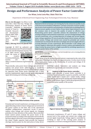
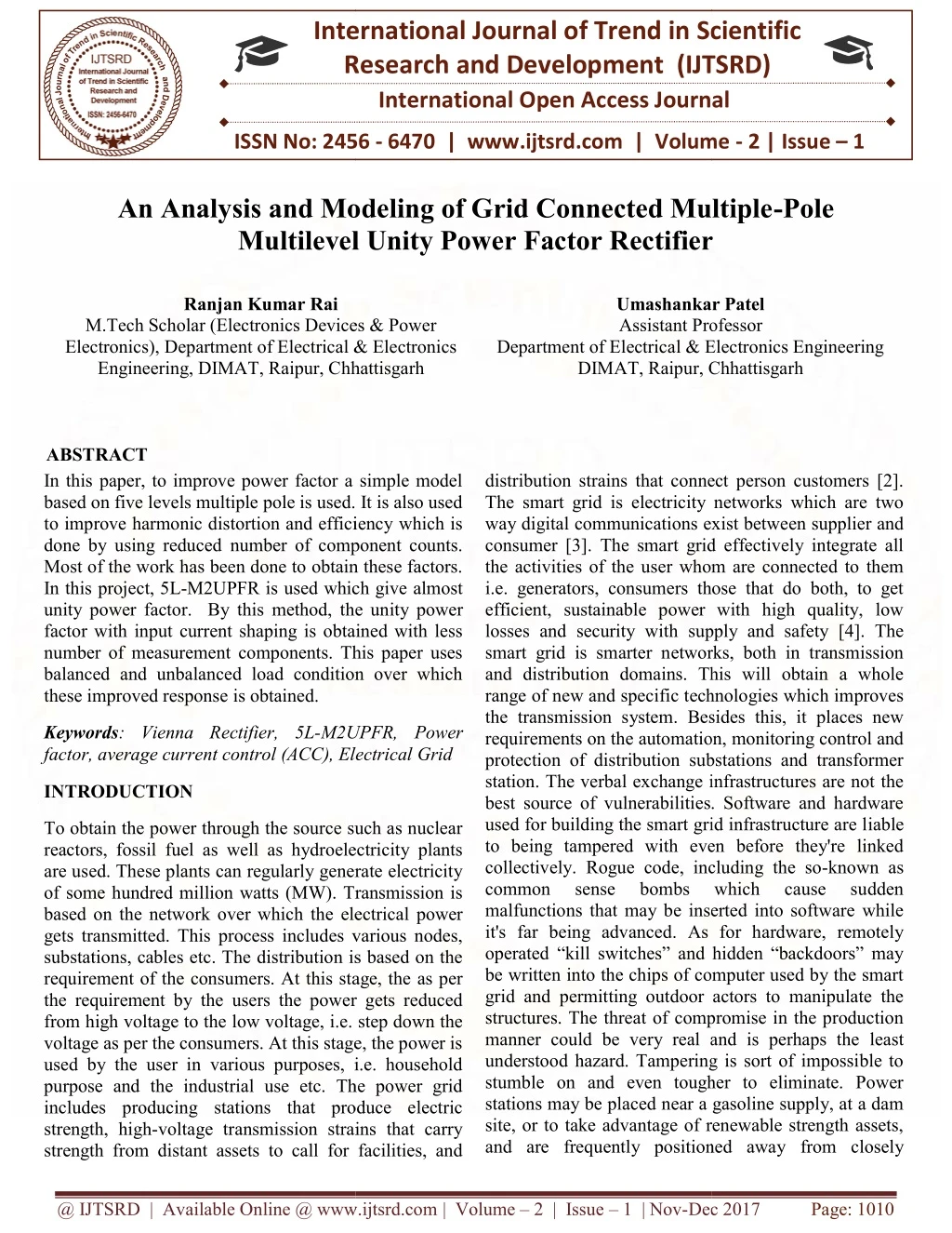
In this paper, to improve power factor a simple model based on five levels multiple pole is used. It is also used to improve harmonic distortion and efficiency which is done by using reduced number of component counts. Most of the work has been done to obtain these factors. In this project, 5L M2UPFR is used which give almost unity power factor. By this method, the unity power factor with input current shaping is obtained with less number of measurement components. This paper uses balanced and unbalanced load condition over which these improved response is obtained. Ranjan Kumar Rai | Umashankar Patel "An Analysis and Modeling of Grid Connected Multiple-Pole Multilevel Unity Power Factor Rectifier" Published in International Journal of Trend in Scientific Research and Development (ijtsrd), ISSN: 2456-6470, Volume-2 | Issue-1 , December 2017, URL: https://www.ijtsrd.com/papers/ijtsrd7137.pdf Paper URL: http://www.ijtsrd.com/engineering/electrical-engineering/7137/an-analysis-and-modeling-of-grid-connected-multiple-pole-multilevel-unity-power-factor-rectifier/ranjan-kumar-rai<br>

E N D
International Research Research and Development (IJTSRD) International Open Access Journal International Open Access Journal International Journal of Trend in Scientific Scientific (IJTSRD) ISSN No: 2456 - 6470 | www.ijtsrd.com | Volume An Analysis and Modeling of Grid Connected Multiple An Analysis and Modeling of Grid Connected Multiple-Pole ISSN No: 2456 | www.ijtsrd.com | Volume - 2 | Issue – 1 An Analysis and Modeling of Grid Connected Multiple Multilevel Unity Power Factor Rectifier Multilevel Unity Power Factor Rectifier Multilevel Unity Power Factor Rectifier Ranjan Kumar Rai Umashankar Patel Umashankar Patel Assistant Professor M.Tech Scholar (Electronics Devices & Power Electronics), Department of Electrical & Electronics Engineering, DIMAT, Raipur, Chhattisgarh M.Tech Scholar (Electronics Devices & Power Department of Electrical & Electronics rofessor Department of Electrical & Electronics Engineering Department of Electrical & Electronics Engineering DIMAT, Raipur, C hhattisgarh Chhattisgarh ABSTRACT In this paper, to improve power factor a simple model based on five levels multiple pole is used. It is also used to improve harmonic distortion and efficiency which is done by using reduced number of component counts. Most of the work has been done to obtain these factors. In this project, 5L-M2UPFR is used which give almost unity power factor. By this method, the un factor with input current shaping is obtained with less number of measurement components. This paper uses balanced and unbalanced load condition over which these improved response is obtained. In this paper, to improve power factor a simple model based on five levels multiple pole is used. It is also used o improve harmonic distortion and efficiency which is done by using reduced number of component counts. Most of the work has been done to obtain these factors. M2UPFR is used which give almost unity power factor. By this method, the unity power factor with input current shaping is obtained with less number of measurement components. This paper uses balanced and unbalanced load condition over which distribution strains that connect person customers [2]. The smart grid is electricity networks which are two way digital communications exist betwe consumer [3]. The smart grid effectively integrate all the activities of the user whom are connected to them i.e. generators, consumers those that do both, to get efficient, sustainable power with high quality, low losses and security with supply and safety [4]. The smart grid is smarter networks, both in transmission and distribution domains. This will obtain a whole range of new and specific technologies which improves the transmission system. Besides this, it places new requirements on the automation, monitoring control and protection of distribution substations and transformer station. The verbal exchange infrastructures are not the best source of vulnerabilities. Software and hardware used for building the smart grid infrastructure are l to being tampered with even before they're linked collectively. Rogue code, including the so common sense bombs malfunctions that may be inserted into software while it's far being advanced. As for hardware, remotely operated “kill switches” and hidden “backdoors” may be written into the chips of computer used by the smart grid and permitting outdoor actors to manipulate the structures. The threat of compromise in the production manner could be very real and is perhaps the understood hazard. Tampering is sort of impossible to stumble on and even tougher to eliminate. Power stations may be placed near a gasoline supply, at a dam site, or to take advantage of renewable strength assets, and are frequently positioned away and are frequently positioned away from closely distribution strains that connect person customers [2]. The smart grid is electricity networks which are two way digital communications exist between supplier and consumer [3]. The smart grid effectively integrate all the activities of the user whom are connected to them i.e. generators, consumers those that do both, to get efficient, sustainable power with high quality, low supply and safety [4]. The smart grid is smarter networks, both in transmission and distribution domains. This will obtain a whole range of new and specific technologies which improves the transmission system. Besides this, it places new e automation, monitoring control and protection of distribution substations and transformer station. The verbal exchange infrastructures are not the best source of vulnerabilities. Software and hardware used for building the smart grid infrastructure are liable to being tampered with even before they're linked collectively. Rogue code, including the so-known as common sense bombs malfunctions that may be inserted into software while it's far being advanced. As for hardware, remotely ted “kill switches” and hidden “backdoors” may be written into the chips of computer used by the smart grid and permitting outdoor actors to manipulate the structures. The threat of compromise in the production manner could be very real and is perhaps the least understood hazard. Tampering is sort of impossible to stumble on and even tougher to eliminate. Power stations may be placed near a gasoline supply, at a dam site, or to take advantage of renewable strength assets, Keywords: Vienna Rectifier, 5L-M2UPFR, Power factor, average current control (ACC), Electrical Grid rent control (ACC), Electrical Grid M2UPFR, Power INTRODUCTION To obtain the power through the source such as nuclear reactors, fossil fuel as well as hydroelectricity plants are used. These plants can regularly generate electricity of some hundred million watts (MW). Transmission is based on the network over which the electrical power gets transmitted. This process includes various nodes, substations, cables etc. The distribution is based on the requirement of the consumers. At this stage, the as per the requirement by the users the power gets reduced from high voltage to the low voltage, i.e. step down the voltage as per the consumers. At this stage, the power is used by the user in various purposes, i.e. household purpose and the industrial use etc. The power grid includes producing stations that produce electric strength, high-voltage transmission strains that carry strength from distant assets to call for facilities, and strength from distant assets to call for facilities, and To obtain the power through the source such as nuclear reactors, fossil fuel as well as hydroelectricity plants are used. These plants can regularly generate electricity of some hundred million watts (MW). Transmission is which which cause cause sudden sudden e electrical power gets transmitted. This process includes various nodes, substations, cables etc. The distribution is based on the requirement of the consumers. At this stage, the as per the requirement by the users the power gets reduced e to the low voltage, i.e. step down the voltage as per the consumers. At this stage, the power is used by the user in various purposes, i.e. household purpose and the industrial use etc. The power grid includes producing stations that produce electric voltage transmission strains that carry @ IJTSRD | Available Online @ www.ijtsrd.com Available Online @ www.ijtsrd.com | Volume – 2 | Issue – 1 | Nov-Dec 2017 Dec 2017 Page: 1010
populated areas. Multilevel converters have become greater appealing for lots industry and academia research. Most of the commercially to be had multilevel inverters require a bulky section-shifted transformer with multiple bridge rectifiers linked at the front aspect [2,5]. However, the quantity and the load of such configuration are large and heavy. In addition, more losses are skilled in the transformer during low utilization because of its middle resistance [6, 7]. Several new transformers less multilevel rectifier topologies with low switching frequency operation had been reported in the literature. The referred to low topologies have performed accurate performance and additionally confirmed that the clear out length may be extensively reduced in spite of the low switching frequency operation. However, each of those topologies has its limitations and disadvantages. For example, a complex manipulate algorithm is needed to stability the flying capacitors of the three-section megastar configured PUC topology. While in the case of RPC DCR topology, simplest two switches are decreased in each phase-leg however the general aspect counts are not notably optimized. Hence, large wide variety of gate drivers and remote gate supplies are still Thus, a decrease cost solution is finished with the discount of measurement sensors needed for the remarks manage loop not like the proposed switching method provided in [8]. In addition to that, top notch dynamic reaction is demonstrated with t performances of both grid voltage and load modern during unbalanced grid condition. International Journal of Trend in Scientific Research and Development (IJTSRD) ISSN: 2456 International Journal of Trend in Scientific Research and Development (IJTSRD) ISSN: 2456 International Journal of Trend in Scientific Research and Development (IJTSRD) ISSN: 2456-6470 populated areas. Multilevel converters have become greater appealing for lots industry and academia research. Most of the commercially to be had multilevel switching frequency operation. However, each of these topologies has its limitations and disadvantages. For e, a complex control algorithm is required to balance the flying capacitors of the three-phase star- configured PUC topology. While in the case of RPC- DCR topology, only two switches are reduced in each leg but the total component counts are not switching frequency operation. However, each of these topologies has its limitations and disadvantages. For instance, a complex control algorithm is required to balance the flying capacitors of the three configured PUC topology. While in the case of RPC DCR topology, only two switches are reduced in each phase-leg but the total component counts are not significantly optimized. shifted transformer inked at the front-stop aspect [2,5]. However, the quantity and the load of such configuration are large and heavy. In addition, more losses are skilled in the transformer during low utilization because of its middle resistance [6, 7]. mers less multilevel rectifier topologies with low switching frequency operation had been reported in the literature. The referred to low-cost topologies have performed accurate performance and additionally confirmed that the clear out length may be ively reduced in spite of the low switching frequency operation. However, each of those topologies has its limitations and disadvantages. For example, a complex manipulate algorithm is needed to stability the Electrical Grid An electrical grid is an interconnected network al energy from distributors to consumers. It consists of the power generation produce electrical power, high-voltage transmission lines that carry power from distant sources to demand centers, and distribution lines that connect An electrical grid is an interconnected network designed to deliver electrical energy to consumers. It consists of stations which produce electrical power, high transmission lines that carry power from distant sources to demand centers, and distribution lines that connect individual customers [2]. Power stations may be positioned near a fuel supply, at a dam website, or to take advantage of renewable electricity r are often located far away regions. They are usually quite large to take advantage of the economies of scale. The electrically powered electricity that is generated is stepped as much as a better voltage at which it con power transmission network. Power stations may be positioned near a fuel supply, at a dam website, or to take advantage of renewable electricity resources, and section megastar- from closely populated configured PUC topology. While in the case of RPC- DCR topology, simplest two switches are decreased in leg however the general aspect counts are not notably optimized. Hence, large wide variety of gate drivers and remote gate supplies are still required. Thus, a decrease cost solution is finished with the discount of measurement sensors needed for the remarks manage loop not like the proposed switching method provided in [8]. In addition to that, top notch dynamic reaction is demonstrated with the expected performances of both grid voltage and load modern-day . They are usually quite large to take advantage The electrically powered electricity that is generated is stepped as much as a better voltage at which it connects to the electrical Multilevel converters are becoming more attractive for many industry and academia research. Most of the commercially available multilevel inverters require bulky phase-shifted transformer with multiple rectifiers connected at the front-end side [ However, the volume and the weight of such configuration are large and heavy. In addition, more losses are experienced in the transformer during low utilization due to its core resistance [6, 7]. Several new transformers less multilevel rectifier topologies with low switching frequency operation have been reported in the literature. Multilevel converters are becoming more attractive for many industry and academia research. Most of the commercially available multilevel inverters require a shifted transformer with multiple-bridge end side [2, 5]. However, the volume and the weight of such configuration are large and heavy. In addition, more losses are experienced in the transformer during low ]. Several new topologies with low switching frequency operation have been reported Fig 1.1: Electrical Grid Fig 1.1: Electrical Grid level rectifier topologies with reduced number of components are found namely: (i) packed U cells multilevel converter (PUC) [22], (ii) reduced diode-clamped rectifier (RPC-DCR) [23 hybrid diode-clamped and flying capacitor rectifier (DCLP-FC) [24]. The mentioned low-cost topologies have achieved good efficiency and also proven that the filter size can be drastically reduced even with the low filter size can be drastically reduced even with the low Recent developments on high incremental voltage Recent developments on high incremental voltage ogies with reduced number of components are found namely: (i) packed U cells The bulk electricity transmission network will pass the , occasionally throughout global boundaries, until it reaches its wholesale customer The bulk electricity transmission network will pass the power long distances, occasionally throughout global boundaries, until it reaches its wholesale customer (commonly the organization that owns the local electric strength distribution network). On arrival at a substation, the power will be stepped down from a transmission level voltage to a distribution degree voltage. As it exits the substation, it enters the Dec 2017 ], (ii) reduced-part count DCR) [23] and (iii) that owns the local electric clamped and flying capacitor rectifier strength distribution network). On arrival at a substation, the power will be stepped down from a l voltage to a distribution degree voltage. As it exits the substation, it enters the cost topologies have achieved good efficiency and also proven that the @ IJTSRD | Available Online @ www.ijtsrd.com Available Online @ www.ijtsrd.com | Volume – 2 | Issue – 1 | Nov-Dec 2017 Page: 1011
distribution wiring. Finally, upon arrival at the provider place, the strength is stepped down once more from the distribution voltage to the specified provider voltage. International Journal of Trend in Scientific Research and Development (IJTSRD) ISSN: 2456-6470 in place of diodes to create a circuit that can regulate the output voltage. Many devices that provide direct current actually generate three-phase AC. For example, an automobile alternator contains six diodes, which function as a full-wave rectifier for battery charging. Three-phase, half-wave circuit An uncontrolled three- phase, half-wave circuit requires three diodes, one connected to each phase. This is the simplest type of three-phase rectifier but suffers from relatively high harmonic distortion on both the AC and DC connections. This type of rectifier is said to have a pulse-number of three, since the output voltage on the DC side contains three distinct pulses per cycle of the grid frequency. Objective To design a cost effective transformer less multiple pole unity power factor rectifier. The proposed three phases M2UPFR utilized only six switched to synthesize a five level input phase voltage stepped waveform, Hence the component counts are greatly reduced. A low switching frequency operation with the average current control implemented for the compensation. (ACC) grid technique harmonic is current Problem Statement From the analysis of various work has already been done it has been found that there are number of problems associated with these works i.e. the model is bulky because of size of the transformer, the losses of the switching are also dominant which occurs at very high frequency. The effect the output power, power factors, efficiency, total harmonic distortions etc. Rectifier A rectifier is an electrical tool that converts alternating current (AC), which periodically reverses direction, to direct current (DC), which flows in one direction. The process is called rectification. Physically, rectifiers take some of the forms, which include vacuum tube diodes, mercury arc valves, copper and selenium oxide rectifiers, semiconductor diodes, silicon-managed rectifiers and different semiconductor switches. synchronous electromechanical switches and motors were used. Early radio receivers, known as crystal radios, used a "cat's whisker" of first-rate twine pressing on a crystal of galena (lead sulfide) to serve as a point-touch rectifier or "crystal detector". Rectifiers have many uses, however, are often found serving as additives of DC energy resources and excessive direct current power transmission systems. silicon-based Historically, totally even Fig 4.3: output voltage on the DC side contains three distinct pulses per cycle Three-phase, full-wave circuit using center-tapped transformer If the AC supply is fed via a transformer with a center tap, a rectifier circuit with improved harmonic performance can be obtained. This rectifier now requires six diodes, one connected to each end of each transformer secondary winding. This circuit has a pulse-number of six, and in effect, can be thought of as a six-phase, half-wave circuit. Before solid state devices became available, the half-wave circuit, and the full-wave circuit using a center-tapped transformer were very commonly used in industrial rectifiers using Three-Phase Rectifiers 3-phase AC input, half- and full-wave rectified DC output waveforms Single-phase commonly used for power supplies for domestic equipment. However, for most industrial and high- power applications, three-phase rectifier circuits are the norm. As with single-phase rectifiers, three-phase rectifiers can take the form of a half-wave circuit, a full-wave circuit using a center-tapped transformer, or a full-wave bridge circuit. Thyristors are commonly used rectifiers are @ IJTSRD | Available Online @ www.ijtsrd.com | Volume – 2 | Issue – 1 | Nov-Dec 2017 Page: 1012
mercury-arc valves [7]. This was because the three or six AC supply inputs could be fed to a corresponding number of anode electrodes on a single tank, sharing a common cathode. With the advent of diodes and thyristors, these circuits have become less popular and the three-phase bridge circuit has become the most common circuit. International Journal of Trend in Scientific Research and Development (IJTSRD) ISSN: 2456 International Journal of Trend in Scientific Research and Development (IJTSRD) ISSN: 2456 International Journal of Trend in Scientific Research and Development (IJTSRD) ISSN: 2456-6470 Reliable behaviour (guaranteeing ohmic mains behaviour) under heavily unbalanced mains voltages and in case of mains failure. voltages and in case of mains failure. This was because the three or iable behaviour (guaranteeing ohmic mains behaviour) under heavily unbalanced mains six AC supply inputs could be fed to a corresponding number of anode electrodes on a single tank, sharing a common cathode. With the advent of diodes and thyristors, these circuits have become less popular and phase bridge circuit has become the most Power Factor The power factor of an AC electrical power system is defined as the ratio of the real power flowing to the load to the apparent power in the circuit,[ dimensionless number in the closed interval of A power factor of less than one means that the voltage and current waveforms are not in phase, reducing the instantaneous product of the two waveforms (V Real power is the capacity of the circuit for performing work in a particular time. Apparent power is the product of the current and voltage of the circuit. Due to energy stored in the load and returned to the source, or due to a non-linear load that distorts the wave shape of the current drawn from the source, the apparent power will be greater than the real power. will be greater than the real power. The power factor of an AC electrical power system is defined as the ratio of the real power flowing to the apparent power in the circuit,[2][5] and is a dimensionless number in the closed interval of −1 to 1. A power factor of less than one means that the voltage and current waveforms are not in phase, reducing the instantaneous product of the two waveforms (V × I). Real power is the capacity of the circuit for performing work in a particular time. Apparent power is the product of the current and voltage of the circuit. Due to energy stored in the load and returned to the source, or Motor-Generator Motor-generator and Rotary converter A small motor generator set A motor-generator set, or the similar rotary converter, is not strictly a rectifier as it does not actually rectify current, but rather generates DC from an AC source. In an "M-G set", the shaft of an AC motor is mechanically coupled to that of a DC generator. generator and Rotary converter A small motor- generator set, or the similar rotary converter, is not strictly a rectifier as it does not actually rectify current, but rather generates DC from G set", the shaft of an AC motor is mechanically coupled to that of a DC distorts the wave shape of The DC generator produces multiphase alternating currents in its armature windings, which a c on the armature shaft converts into a direct current output; or a homopolar generator produces a direct current without the need for a commutator. M are useful for producing DC for railway traction motors, industrial motors and other high applications, and were common in many high D.C. uses (for example, carbon-arc lamp projectors for outdoor theaters) before high-power semiconductors became widely available. The DC generator produces multiphase alternating currents in its armature windings, which a commutator on the armature shaft converts into a direct current output; or a homopolar generator produces a direct current without the need for a commutator. M-G sets are useful for producing DC for railway traction motors, industrial motors and other high-current applications, and were common in many high-power the current drawn from the source, the apparent power A negative power factor occurs when the device (which is normally the load) generates power, which then flows back towards the source, which is normally A negative power factor occurs when the device (which is normally the load) generates power, which then flows back towards the source, w considered the generator [6] power system, a load with a low power factor draws more current than a load with a high power factor for the same amount of useful power transferred. The higher currents increase the en distribution system, and require larger wires and other equipment. Because of the costs of larger equipment and wasted energy, electrical utilities will usually charge a higher cost to industrial or commercial customers where there is a lo loads with low power factor (such as induction motors) can be corrected with a passive network of capacitors or inductors. Non-linear loads, such as rectifiers, distort the current drawn from the system. In such cases, active or passive power factor correction may be used to counteract the distortion and raise the power factor. The devices for correction of the power factor may be at a central substation, spread out over a distribution system, or built into power-consuming equipment. consuming equipment. [7] [22]. In an electric power system, a load with a low power factor draws more current than a load with a high power factor for the same amount of useful power transferred. The higher currents increase the energy lost in the distribution system, and require larger wires and other equipment. Because of the costs of larger equipment and wasted energy, electrical utilities will usually charge a higher cost to industrial or commercial customers where there is a low power factor. Linear loads with low power factor (such as induction motors) can be corrected with a passive network of capacitors linear loads, such as rectifiers, distort the current drawn from the system. In such cases, active ive power factor correction may be used to counteract the distortion and raise the power factor. The devices for correction of the power factor may be at a central substation, spread out over a distribution arc lamp projectors for power semiconductors Fig 4.4: RC-Filter Rectifier Filter Rectifier Vienna Rectifier The Vienna Rectifier is a pulse-width modulation rectifier, invented in 1993 by Johann W. Kolar. provides: width modulation rectifier, invented in 1993 by Johann W. Kolar. It Three-phase three-level three-switch PWM rectifier with controlled output voltage switch PWM rectifier MULTIPLE-POLE UNITY POWER FACTOR RECTIFIER TOPOLOGY POLE UNITY POWER FACTOR Three-wire input, no connection to neutral. Ohmic mains behaviour[citation needed Boost system (continuous input current). Unidirectional power flow. High power density. Low conducted common-mode EMI emissions. Simple control to stabilize the neutral point potential. Low complexity, low realization effort Low switching losses. wire input, no connection to neutral. Ohmic mains behaviour[citation needed] Boost system (continuous input current). Basic Operating Principle A multiple-pole unity power factor rectifier topology with balanced load which is shown in Figure 2 is built on the basis of three-level VIENNA rectifier cells in each phase-leg. The concept of inverter which is similar to multiple-pole structure is used in multilevel diode circuit [9]. Hence, the output terminals of both the circuit, i.e. VIENNA rectifier cells which are the circuit, i.e. VIENNA rectifier cells which are pole unity power factor rectifier topology with balanced load which is shown in Figure 2 is built level VIENNA rectifier cells in The concept of inverter which is pole structure is used in multilevel diode circuit [9]. Hence, the output terminals of both mode EMI emissions. Simple control to stabilize the neutral point Low complexity, low realization effort @ IJTSRD | Available Online @ www.ijtsrd.com Available Online @ www.ijtsrd.com | Volume – 2 | Issue – 1 | Nov-Dec 2017 Dec 2017 Page: 1013
International Journal of Trend in Scientific Research and Development (IJTSRD) ISSN: 2456-6470 linked to the respective dc capacitors with resource of balancing circuit [10, 11]. The overall performance of this method is synthesized which is based on switching state selection and the direction of phase current in which each cell is characterized with the multiple level input voltage stepped waveform. Figure 4: The Load current observer Voltage Control The voltage control carried at the outer loop is regulated with a the proportional integral (PI) controller which is expressed as follows Where, Figure 2: Unidirectional 5L-M2UPFR with the balancing circuit Kp represents the proportional gain of the dc-link voltage regulator Controller Design ti represents the settling time of the dc-link voltage tracking. Unity Power Factor Control The load current and grid voltage is controlled by using the power factor control as shown in figure 3. The controller structure is constructed synchronous reference frame (SRF) current control [12]. To limit the control bandwidth, the complicated phase locked loop design is used in the transformation. The approximated value of the proportional gain (Kp) is obtained from the energy storage model. According to stability criteria, the proportional gain of the control system expressed in below equation. using Current Control The grid current control technique of the active rectifier which are carried out by inner loop circuit is classified into four categories, these are space vector modulation (SVM) [13, 14], fix hysteresis band current control (FHBCC) [12, 15], variable hysteresis band current control [16] and ACC [15, 17]. The SVM scheme uses high computational effort; this is due to complex sector control algorithm which is required for the higher voltage stepped level rectifier topology [18]. Both the problem associated with HBCC and ACC can be overcome by using SVM scheme. However, The circuit of FHBCC scheme exhibits very complex circuits, which is the only disadvantage of this variable switching frequency which also increase the complexity of the design of the input inductance filter. Figure 3: Block diagram of the unity power factor controller with the grid voltage and load current observers. On this basis of the electrical control system there are two types of control is used i.e. voltage and current control. These two control mechanism is applied to both the circuits i.e. at outer loop and at the inner loop. The voltage control carried at the outer loop and current control carried at the inner loop [9]. The dc equivalent capacitor current is calculated by the outer loop control which regulates the output dc link voltage. Meanwhile, the load current is formulated from the power balanced principle. @ IJTSRD | Available Online @ www.ijtsrd.com | Volume – 2 | Issue – 1 | Nov-Dec 2017 Page: 1014
International Journal of Trend in Scientific Research and Development (IJTSRD) ISSN: 2456-6470 (THD) is obtained. Due to less number of sensors, the components count also gets reduced. Most important is that we can design light weight and high power density using this method. ACKNOWLEDGEMENT Expression of giving thanks are just a part of those feeling which are too large for words, but shall remain as memories of wonderful people with whom I have got the pleasure of working during the completion of this work. I would like to express my deep and sincere gratitude to my supervisor, Mr. Umashankar Patel, Assistant Professor in Department of Electrical & Electronics Engineering, DIMAT, Raipur. His wide knowledge and his logical way of thinking have been of great value for me. His/her understanding, encouraging and personal guidance have provided a good basis for the present work. I am grateful to DIMAT, Raipur (C.G.) which helped me to complete my work by giving encouraging environment. Figure 5: Energy stored model Figure 6: Peak detector of the grid voltage for the reference sinusoidal wave Grid Voltage References For the proper rectifier configurations various observer strategies had already been proposed [19-21]. Besides these benefit of disposing of the sensors which are needed, this approach reduces the converter size and also offers a lower production cost as well. This simple model will eliminate the problem of 3 levels multiple pole which is total harmonic distortion. To derive and find the ac and dc voltages, the statistics of three phase grid currents are sufficient, but very high dc-link voltage ripples are experienced throughout the computational process. Hence, high cutting edge total harmonic distortion inside the grid is inflicting. 1)United States of America, H.R. 6582: American Energy Manufacturing Technical Corrections Act, 2012. 2)Kouro, S., Malinowski, M., Gopakumar, K., et al.: ‘Recent advances and industrial applications of multilevel converters’, IEEE Trans. Ind. Electron., 2010, 57, pp. 2553–2580. 3)Commission Communication from the commission to the european parliament, the council, the European economic and social committee and the committee of the regions. Smart Grids: from innovation to deployment 2011. of the European communities. 4)http://ec.europa.eu/energy/gas_electricity/smartgrid s/taskforce_en.htm. 5)Miranbeigi, M., Iman-Eini, H., Asoodar, M.: ‘A new switching strategy for transformer-less back- to-back cascaded H-bridge multilevel converter’, IET Power Electron., 2014, 7, pp. 1868–1877. Figure 7: Grid voltage observer CONCLUSION 6)Daher, S., Schmid, J., Antunes, F.L.M.: ‘Multilevel inverter topologies for stand-alone PV systems’, IEEE Trans. Ind. Electron., 2008, 55, pp. 2703– 2712. This proposed topology, i.e. 5 level 5L-M2UPFR method provides very high reliability over the three phase power supply at extreme unbalanced condition of grid. These three conditions will help in the design of the method by which we can obtain the system with reduced number of sensors which improves the failures of the system and by this method almost unity power factor with very less total harmonics distortion 7)Steimer, ‘Transformerless medium voltage drives’. 2011 IEEE Energy P.K., Winkelnkemper, multi-level M.: converter based @ IJTSRD | Available Online @ www.ijtsrd.com | Volume – 2 | Issue – 1 | Nov-Dec 2017 Page: 1015
International Journal of Trend in Scientific Research and Development (IJTSRD) ISSN: 2456-6470 17)Jong-Won, implemented average current-mode control in discontinuous conduction mode PFC rectifier’, IEEE Trans. Power Electron., 2012, 27, pp. 3363– 3373. Conversion Congress and Exposition (ECCE), 2011, pp. 3435–3441. S., Bo-Hyung, C.: ‘Digitally 8)Gabriel, O.H.P., Maswood, A.I., Ziyou, L., et al.: ‘Input current shaping of five-level multiple-pole VIENNA rectifier topologies component and better performance’. Presented at the 39th Annual Conf. of the IEEE Industrial Electronics Society, IECON 2013–, 2013. with reduced 18)Ide, ‘Investigation of low cost control schemes for a selected 3-level switched Nineteenth Int. Telecommunications Energy Conf., 1997. INTELEC 97, 1997, pp. 413–418. P., Froehleke, N., Grotstollen, H.: mode rectifier’. 9) Ooi, G.H.P., Maswood, A.I., Ziyou, L.: ‘Five-level multiple-pole PWM AC-AC converters with reduced components count’, IEEE Trans. Ind. Electron., 2015, 62, pp. 4739–4748. 19)Ohnuki, T., Miyashita, O., Lataire, P., et al.: ‘Control of a three-phase PWM rectifier using estimated AC-side and DC-side voltages’, IEEE Trans. Power Electron., 1999, 14, pp. 222–226. 10)Hatti, N., Kondo, Y., Akagi, H.: ‘Five-level diode- clamped PWM converters connected back-to-back for motor drives’, IEEE Trans. Ind. Appl., 2008, 44, pp. 1268–1276. 20)Wang, B., Venkataramanan, G., Bendre, A. ‘Unity power factor control for three-phase three level rectifiers without current sensors’, IEEE Trans. Ind. Appl., 2007, 43, pp. 1341–1348. 11)Ajami, A., Shokri, H., Mokhberdoran, A.: ‘Parallel switch-based chopper circuit for DC capacitor voltage balancing in diode-clamped multilevel inverter’, IET Power Electron., 2014, 7, pp. 503– 514. 21)Ghosh, R., Narayanan, G.: ‘Generalized feed forward control of single-phase PWM rectifiers using disturbance observers’, IEEE Trans. Ind. Electron., 2007, 54, pp. 984–993. 12)Maswood, A.I., Fangrui, L.: ‘A unity-power-factor converter using the synchronous reference-frame- based hysteresis current control’, IEEE Trans. Ind. Appl., 2007, 43, pp. 593–599. 22)Ounejjar, Y., Al-Haddad, K., Grégoire, L.A., et al.: ‘Packed U cells multilevel converter topology: theoretical study and experimental validation’, IEEE Trans. Ind. Electron., 2011, 58, pp. 1294– 1306 Fig. 11 Input voltage and current performance of a 5L- M2UPFR topology under extreme unbalanced grid condition a Input pole voltage b dc- link voltage (upper trace), grid phase voltage and line current (lower trace) c THD of line current IET Power Electron., 2016, Vol. 9, Iss. 7, pp. 1437– 1444 & The Institution of Engineering and Technology 2016 1443. 13)Barbi, I., Batista, F.A.B.: ‘Space vector modulation for two-level unidirectional PWM rectifiers’, IEEE Trans. Power Electron., 2010, 25, pp. 178–187. 14)Raj, P.H., Maswood, A.I., Ooi, G.H.P., et al.: ‘Voltage balancing technique in a space vector modulated 5-level multiple-pole multilevel diode clamped inverter’, IET Power Electron., 2015, 8, pp. 1263–1272. 15)Maswood, A.I., Al-Ammar, E., Liu, F.: ‘Average and hysteresis current-controlled three-phase three- level unity power factor rectifier operation and performance’, IET Power Electron., 2011, 4, pp. 752–758. 23)Corzine, K.A., Baker, J.R.: ‘Reduced-parts-count multilevel rectifiers’, IEEE Trans. Ind. Electron., 2002, 49, pp. 766–774. 24)Itoh, J.I., Noge, Y., Adachi, T.: ‘A novel five-level three-phase PWM rectifier with reduced switch count’, IEEE Trans. Power Electron., 2011, 26, pp. 2221–2228. 16)Fangrui, L., Maswood, A.I.: ‘A novel variable hysteresis band current control of three-phase three- level unity PF rectifier with constant switching frequency’, IEEE Trans. Power Electron., 2006, 21, pp. 1727–1734. @ IJTSRD | Available Online @ www.ijtsrd.com | Volume – 2 | Issue – 1 | Nov-Dec 2017 Page: 1016