Download
1 / 4
40 likes | 45 Views
This paper investigates based on microcontroller medicine reminder alarm system. This system includes the DS1307 Real Time Clock RTC module, L298N motor driver, DC motor, I2C Liquid Crystal Display LCD module, four pushbuttons and buzzer. Arduino UNO is used to activate the whole system. Four types of push button enter the time for the person to take medicine. The clock module is used to set up time and LCD is used to display time for the taking medicine. The buzzer is used to alarm the time for taking medicine. The motor driver is used to drive the DC motor which controls the opening and closing function of the medical box. Ni Ni San Hlaing | San San Naing "Alarm System for Medicine Reminder Based on Microcontroller" Published in International Journal of Trend in Scientific Research and Development (ijtsrd), ISSN: 2456-6470, Volume-3 | Issue-5 , August 2019, URL: https://www.ijtsrd.com/papers/ijtsrd26518.pdf Paper URL: https://www.ijtsrd.com/engineering/electronics-and-communication-engineering/26518/alarm-system-for-medicine-reminder-based-on-microcontroller/ni-ni-san-hlaing<br>

E N D
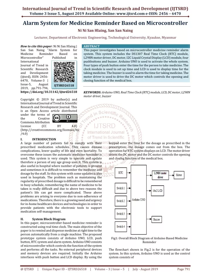
International Journal of Trend in Scientific Research and Development (IJTSRD) Volume 3 Issue 5, August 2019 Available Online: www.ijtsrd.com e-ISSN: 2456 – 6470 Alarm System for Medicine Reminder Based on Microcontroller Ni Ni San Hlaing, San San Naing Lecturer, Department of Electronic Engineering, Technological University, Kyaukse, Myanmar How to cite this paper: Ni Ni San Hlaing | San San Naing "Alarm System for Medicine Reminder Microcontroller" International Journal of Trend in Scientific Research and Development (ijtsrd), ISSN: 2456- 6470, Volume-3 | Issue-5, August 2019, pp.791-794, https://doi.org/10.31142/ijtsrd26518 Copyright © 2019 by author(s) and International Journal of Trend in Scientific Research and Development Journal. This is an Open Access article distributed under the terms of the Creative Commons Attribution License (CC (http://creativecommons.org/licenses/by /4.0) I. INTRODUCTION A large number of patients fail to comply with their prescribed medication schedules. This causes disease complications, lower quality of life and even mortality. To overcome these issues the automatic medicine reminder is used. This system is very simple to operate and update therefore a person of any age group uses it. This system is also useful in hospital where number of patients is present and sometimes it is difficult to remember the medicine and dosage by the staff. So this system with some updates is also used in hospitals. The problem such as maintaining the regularity of prescribed dosage is difficult to be remembered in busy schedule, remembering the name of medicine to be taken is really difficult and due to above two reasons the patient’s life can get more complicated. These above problems are arising to everyone due to non-adherence of medications. Therefore, there is a growing need and urgency for in-home healthcare devices and technologies in order to provide patients with the electronic tools to support medication self-management. II. System Block Diagram In this paper, microcontroller-based medicine reminder is constructed using real time clock. The main objective of the paper is to remind and dispense medicine at right time to the person automatically from a single machine. The proposed prototype system consists of Arduino UNO, LCD, push button, RTC system and alarm system. Arduino UNO consists of microcontroller which controls the function of the system and performs all the tasks. No external peripheral devices and memory devices are required. Initially the Arduino interfaces with push button and LCD display. By using the ABSTRACT This paper investigates based on microcontroller medicine reminder alarm system. This system includes the DS1307 Real Time Clock (RTC) module, L298N motor driver, DC motor, I2C Liquid Crystal Display (LCD) module, four pushbuttons and buzzer. Arduino UNO is used to activate the whole system. Four types of push button enter the time for the person to take medicine. The clock module is used to set up time and LCD is used to display time for the taking medicine. The buzzer is used to alarm the time for taking medicine. The motor driver is used to drive the DC motor which controls the opening and closing function of the medical box. KEYWORDS: Arduino UNO, Real Time Clock (RTC) module, LCD, DC motor, L298N motor driver, buzzer Based on in Published IJTSRD26518 BY 4.0) keypad enter the time for the dosage as prescribed in the prescription; the dosage comes out from the box. The operation for RTC system displays on LCD. The motor driver drives the DC motor and the DC motor controls the opening and closing function of the medical box. Fig1: Overall Block Diagram of Arduino Based Medicine Reminder The flowchart shown in Fig.2 is for the operation of the system. In this system, Arduino UNO is used as the control system consists of @ IJTSRD | Unique Paper ID – IJTSRD26518 | Volume – 3 | Issue – 5 | July - August 2019 Page 791
International Journal of Trend in Scientific Research and Development (IJTSRD) @ www.ijtsrd.com eISSN: 2456-6470 Step 1 : Start Step 2 : Initialize the input and output pins Step 3 : Set time from a user by pressing push button Step 4 : Check select time reaches. If the select time reaches, buzzer occurs ON state and motor drive forward. Otherwise, the user set the time again. Step 5 : Press any button. If press any button, buzzer occurs OFF state and the motor goes backward condition. Otherwise, the buzzer is existing ON state and motor is also existing forward condition. Step 6 : Date and time display on LCD Step 7 : Exit if (digitalRead(2))selecttime=4; if (digitalRead(3))selecttime=5; if (digitalRead(4))selecttime=6; if (digitalRead(5))selecttime=7; C.Software Implementation for Medical Box Open and Buzzer ON The programming language is written for medical box open and buzzer ON. At the loop function includes the pin 6 of the motor driver is high, pin 7 of the motor driver is low and the buzzer is high. At this time, the medical box is opened and the buzzer is ON. digitalWrite(6,HIGH); digitalWrite(7,LOW); digitalWrite(8,HIGH); D.Software Implementation for Medical Box Close and Buzzer OFF The programming language is written for a medical box close and buzzer OFF... At the loop function includes the pin 6 of the motor driver is low, pin 7 of the motor driver is high and a buzzer is low. At this time, the medical box is closed and a buzzer is OFF. (digitalWrite (6,LOW); digitalWrite (7,HIGH); digitalWrite (8,LOW); E.Implementation by Hardware START Initialize all I/O pin LCD start showing “ Select Time” Set time from user No Reach selected time? Yes Buzzer ON and DC motor drive forward 12V 12V OUT1 OUT1 GND GND L298N DC motor L298N OUT2 OUT2 No Press any button? IN1 IN2 IN1 IN2 Yes Push Button Buzzer 10k 10k Buzzer OFF and DC motor drive backward 330 330 GND 6 7 2 3 4 5 D4 Np:Ns GND D1 8 Arduino UNO 1 78052 Display LCD AC Vcc SDA SDA SCL 3 RTC module SCL 1000µF100µF . D2 D3 5V END Vcc Vcc GND Fig 2: Overall System Flowchart A4 A5 GND III. A.Software Implementation The software implementation is the Arduino IDE based software environment. A program written with the Arduino IDE is called a sketch. Sketches are saved on the development computer as text files with the file extension .ino. Arduino Software (IDE) saved sketches with the extension .pde. A minimal Arduino C/C++ program consists of only two functions: setup (): This function is called once when a sketch starts after power-up or reset. It is used to initialize variables, input and output pin modes, and other libraries needed in the sketch. Loop (): After setup () function exits (ends), the loop () function is executed repeatedly in the main program. It controls the board until the board is powered off or is reset. B.Software Implementation for RTC Module The software programming language for the RTC module is very simple. RTC module process is also done in setup loop. The setup function for RTC module is declared select time of each button. These buttons are used to change select time. Implementation SDA SCL Vcc GND I2C module 16 x 2 LCD 16 x 2 LCD Fig 3: Overall Circuit Diagram of the system In this system, Arduino UNO is used for controlling the whole system. DS1307 real time clock chip is used for running the time accurately and to prevent the time after light failure by using 3V li-ion battery connected with this real time clock chip at pin 3. SDA and SCL pin of real time clock chip is directly connected with SDA and SCL pin of Arduino respectively. The main supply VCC is connected with 5V DC supply circuit. Liquid Crystal Display (LCD) is connected with I2C to reduce from 16 pins to 4 pins. SDA and SCL pin of I2C module is connected with A4 and A5 pin of Arduino respectively. The power supply pin VCC is directly connected with the 5V DC power supply circuit. The pin 8 of Arduino is connected with buzzer. The ground pin of the buzzer is @ IJTSRD | Unique Paper ID – IJTSRD26518 | Volume – 3 | Issue – 5 | July - August 2019 Page 792
International Journal of Trend in Scientific Research and Development (IJTSRD) @ www.ijtsrd.com eISSN: 2456-6470 connected with the ground pin of Arduino. Four push buttons are connected with pin 2, 3, 4 and 5 of Arduino respectively. There are 15 pins in L298N motor driver but only 6 pins are used in this system. IN1 and IN2 which is connected to pin number 6 and 7 of Arduino respectively. OUT1 and OUT2 pin of L298N motor driver are connected with DC motor. The power supply pin is connected with a 12V DC power supply. Figure 3. Shows overall circuit diagram. To set the alarm time for medication, push button connected with pin 2 of Arduino is pressed. After pressing this button LCD shows select time 4AM. At this time, the green LED connected with pin 7 of the motor drive is high. And then, the time set select time for medication by using push buttons connected with pin 3, 4 and 5 of Arduino. After select time at 4AM, LCD shows select time at 5AM. Now using the previous process set the time again. And after second- time set, LCD shows again select time reaches the select time, the buzzer is ON and L298N motor driver drives DC motor for the opening of the medical box. At this time, a red LED connected with pin 6 of the motor driver is high. By pressing any push button the buzzer is OFF and the medical box is closed. When an alarm occurs LCD indicates date and time. IV. Results This section is test and results of the whole system. Attesting of the Arduino based medicine reminder, LCD shows “select time”. Buttons use for setting time and to start the real time clock module. When the timer reaches the set time, DC motor goes forward and the buzzer is ON. After pressing any button, DC motor goes backward and a buzzer is OFF. At the description of this section includes eight parts of the test and results. Testing of Select Time This testing is the text of select time display on LCD when the incipient condition of Arduino based medicine reminder system. Fig: 6.shows testing of selects time. Testing of Select Time 4AM This testing is select time 4AM when the user press push button that is connected with pin 2 of Arduino. Fig:7. shows the testing of select time at 4AM. Testing of Select Time 5AM Testing of select time 5AM occurs when the user press push button that is connected with pin 3 of Arduino. Fig 4: Testing of Arduino Based Medicine Reminder Output DC Voltage Testing for Power Supply Section This testing is an output DC voltage for the power supply section of the Arduino based medicine reminder system. Fig: 8.shows testing of select time 5AM. Testing of Select Time 6AM This testing is select time 6AM when the user press push button that is connected with pin 4 of Arduino. Fig: 5.Output DC Voltage Testing for Power Section @ IJTSRD | Unique Paper ID – IJTSRD26518 | Volume – 3 | Issue – 5 | July - August 2019 Page 793
International Journal of Trend in Scientific Research and Development (IJTSRD) @ www.ijtsrd.com eISSN: 2456-6470 V. There are many systems which are serving for the same purpose. But these systems are difficult to use, nonmobile, expensive and complex process. The proposed system overcomes these problems. The Arduino based medicine reminder is simple to use, affordable, better accuracy. This system is helpful for every age group and can also be used in a hospital for a group of people. This system definitely reduces the bad effect caused due to the wrong intake of medicine. This system can be made more effective by upgrading its few features. In the future due to manual work, the available system can become more time-consuming. So in the given future, an attempt can be made to implement fully automatic medication reminder system based on handwritten character recognition. This is achieved with the help of an artificial neural network. A neural network is very effective to decipher any character of any language. The accuracy of character recognition is more important. So the accuracy of characters needs to improve by adding probability to each character. For example, a character Q is very less easy to find because character Q is more often mistaken with O in most of the OCR systems. The proposed system only set the reminders in the built-in calendar application of the mobile. This reminder reminds the user about their medicine intake schedule. The system which is implementing to give the reminder about doctor’s next appointment. It also tells the user of the end of the medicines. The scheduled reminder don’t suggest any kind of medicine, a dose of medicine, etc. VI. REFERENCES [1]Anonymous: wiki.sunfounfer.cc/index.php?...Motor…,https://www.s t.com/.../motor-drivers/L298.., (2017). Conclusion Fig: 9. shows testing of select time 6AM. Testing of Select Time 7AM Testing of select time 7AM occurs when the user press a push button that is connected with pin 5 of Arduino. [2]Anonymous: https://data.kent-fei.tuke.sk/.../LCD/20..., (2016). [3]Muammer, G., Hakan, A., Abdullah, Y.: Ethernet Automated Pill Dispenser, Eastern Mediterranean University, 1-131, (2016). Fig: 10. Shows testing of select time 7AM [4]Urvashi, S., Chetna, C., Himina, S., Anjila, S.: Arduino Based Medicine Reminder, 37-45, (2016). Result of Medical Box Open and Buzzer ON This result condition is medical box open and buzzer ON when the timer reaches the selected time. [5]Guillermo, J., G.: Smart Pill Dispenser For Depent People, 1-114, (2015). [6]Anonymous: www.geeetech.com/, (2012). [7]Anonymous: https://www.sparkfun.com/.../L298-H..., (2000). Fig: 11. shows the result of medical box and buzzer. @ IJTSRD | Unique Paper ID – IJTSRD26518 | Volume – 3 | Issue – 5 | July - August 2019 Page 794