Download
1 / 65
650 likes | 824 Views
Basic Microcontroller System. Chapter 2 Introduction to M68HC11 Hardware. Notation. We will use special characters to represent a value in various number systems: For Hex numbers, we’ll use a $ Ex: 3F 16 will be written as $3F For Binary numbers, we’ll use a %

E N D
Basic Microcontroller System Chapter 2 Introduction to M68HC11 Hardware
Notation • We will use special characters to represent a value in various number systems: • For Hex numbers, we’ll use a $ • Ex: 3F16 will be written as $3F • For Binary numbers, we’ll use a % • Ex: 10102 will be written as %1010 • For decimal numbers, we will a blank • Ex: 2310 = 23
Our Specific HC11 • Our lab boards are populated with ICs (in U1) having the part number (visible on the package): • MC68HC11E9BCFN2 • What this means (see Freescale HC11 Ref. Man., Figure 1-3): • MC - Motorola Corp., fully specified & qualified part • 68 - Numeric designator • A broad spectrum of different Motorola CPUs all include this code • HC - High-density CMOS – Technology used in chip • CMOS = Complementary Metal-Oxide-Semiconductor • Operating voltage range VDD = 5V DC ± 10% • 11 - Numeric designator for a particular 8-bit MCU core & ISA • E - E-series line of microcontroller ICs, • Includes 4 on-chip peripheral interface ports • 9 - IC version with a specific on-chip memory configuration • Includes 512B RAM, 512B EEPROM, and 12K ROM on-chip • B - Buffalo monitor software included in ROM • C - Operating temperature range −40°C to 85°C. • FN - Package type: 52-pin Plastic Leaded Chip Carrier (PLCC) • 2 - Maximum clock speed (2 MHz)
Microcontroller-Based System To I/O CPU: Central Processor Unit I/O: Input/Output Memory: Program and Data Bus: Address signals, Control signals, and Data signals Microcontroller e.g. M68HC11
Inside the CPU • Block diagram of a simple, generic CPU: CPU Instruction Decoder & CPU Controller Interruptsignals ControlFSM Control signals tristate buf Arithmetic- Logic Unit PC Bus tomemorysystem &I/O ports A ALU mux B … mux mux Datapath mux Writeports Read ports Registers
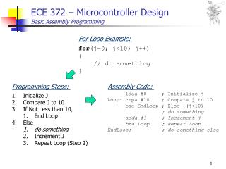
Typical CPU Operation Cycle • Fetch next sequential instruction (if not jumping): • Current PCt (program counter) sent to ALU, added to 1 • PCt+1 result is written to memory address bus, & to next PCt+1 • Memory system returns the instruction byte located at [PCt+1] • The controller unit reads and decodes the instruction • Sets control signals appropriately to begin instruction execution • Instruction execution: • Data are moved around appropriately for the instruction • Between memory, registers, and ALU (where data are processed) • The instruction’s execution may take 1 or more clock cycles • Depending on the precise instruction type (and maybe on data). • Execution sequence performed by an FSM inside controller • Or, by a microcode program… • A sequence of control words in a ROM inside the controller
Registers and Memory Arrays Introduction to Registers
D-FF Positive Edge Triggered Symbol Equation (rising clock) Truth Table D-FF Stores 1 bit of data
4-bit Memory Register Stores 4 bits of data
8-bit Memory Register D[7..0] Q[7..0] Stores 8 bits of data
68HC11 Register Set Clock is implied
A,B and D Registers D Register is the 16 bit concatenation of the A and B registers. Ex: Let A=$23 and B=$EF then D=$23EF
Index Registers 16 bit registers
Stack Pointer The stack pointer is used to access a special section of memory called the Stack.
Condition Code Register • Special Register used for control and provide arithmetic information to programmer and CPU. Condition Code Register
Program Counter The program counter points to the next byte which will be “fetched” from memory. It is not under direct control of the programmer.
Memory Used for Program and Data Storage
Memory Arrays • Two major types • Volatile • Data are lost when power is removed • E.g. • SRAM – Static Random Access Memory • DRAM – Dynamic Random Access Memory • Generically referred to as RAM (Random Access Memory) • Although non-volatile RAM exists as well • Non-Volatile • Data are retained when power is removed • E.g. • EEPROM – Electrically Erasable Programmable Read Only Memory • EPROM - Erasable Read Only Memory • Generically referred to as ROM (Read Only Memory)
Memory Arrays • RAM • Read from and write to RAM • Used for Data and Program Storage • ROM • Only read from ROM • Used for Program Storage only • Also store “Constant” data. • Special program stored in ROM • “Boot” Program or “Loader” Program • This is the program that is executed when the microcontroller is “reset”
Memory Arrays • To “access” memory we must have an “address” • In the 68HC11, we have a 16 bit address bus, so • We can access 64K (64,53610) or $10000 memory locations. • Addresses are numbered from $0000 to $FFFF • Each memory location is 8 bits wide. • Note: in general, • # of address bits = log2 (# of memory locations) • Ex: Original IBM PC had a 1MByte address space # of address bits = log2(1024×1024) = log2(1,048,576) = 20 bits
Sample Memory Map $0000 System RAM User Program RAM Data User Data User Stack Stack System ROM $FFFF
Default Memory Maps of HC11E9 (From the HC11E series datasheet)
Memory map on CME11E9-EVBU board, in the usual (expanded) mode (From the board’smanual)
Addressing Modes • Microcontrollers/Microprocessors use a variety of “addressing modes” to refer to data which may be stored in a variety places, • Frequently at locations in the memory array. • We’ll examine the addressing modes that are available in the 68HC11 • These are fairly representative of the sorts of modes that you will find in typical modern processors.
Addressing Modes • Register (Inherent) Addressing • Immediate Addressing • Direct Memory Addressing • Extended Direct Memory Addressing • Register Index Addressing • Register Indirect Addressing • Relative Addressing
Register (Inherent) Addressing • The internal register set of the controller (or processor) is accessed. • Faster than regular memory access. • Use fewer bits to code this type of instruction • Generally only a 1-byte opcode is needed. • Example: • TAB = Transfer contents of register A to register B • Function (RTL semantics): B A (B gets A) • Roughly equivalent C code: • register char a,b; … b = a; • if C variables “b” & “a” were allocated to registers b & a • Machine code for TAB: only 1 byte, namely hex $16 = binary %00011010. Opcode for TAB.
Immediate Addressing • The data for the instruction is coded right along with the instruction. That is, it immediately follows the instruction in memory. • It’s constant data. → It can be stored in ROM • Immediate data can generally be either 8-bit or 16-bit • Although some instructions may only take 1 or the other • Use the # symbol to indicate immediate mode! • Otherwise, you will be using Direct addressing • This is something completely different! • Examples of immediate addressing: • LDAA #$64 - Load accumulator A with $64 (hex) • Machine code: 2 byte seq.: $86 (opcode), $64 (operand) • C code equivalent: register char a = 0x64; • LDX #$1234 - Load Register X with $1234 (Hex) • Machine code: 3 bytes: $CE, $12, $34. • opcode, MS (high) byte of $1234, LS (low) byte of it • C code equivalent: register short x = 0x1234;
Direct Memory Addressing • This mode accesses the memory directly • In the 68HC11: • Direct addressing accesses only locations $0000-$00FF • Requires only 8 bits for address (256 locations) • CPU automatically sets upper byte of address to $00 • Example: LDAA $64: Loads Register A with Data stored in memory location $0064 • Machine code: $96, $64 • RTL semantics: A ← Mem[$0064] • C code equivalent: register char a = *(0x64); • Register A gets set to the contents of address $0064
Extended Direct Memory Addressing • Extended Direct Memory accesses the entire 64K address space: $0000 - $FFFF • This is just called “direct” mode on many other CPUs • Example: LDAA $1234 • Loads Register A with data stored in memory location $1234 • Requires 16 bits (2 bytes) for the address • Machine code: $B6, $12, $34 • RTL semantics: A ← Mem[$1234] • C code equivalent: register char a = *(0x1234); • Register A is loaded with the contents of memory location $1234
Register Indexed Addressing • Effective address is the sum of an index register (X or Y) and an 8-bit (unsigned) constant offset • This type of addressing is called displacement addressing in many other architectures. • Example: LDX #$A13F X $A13F LDAA $0A,XA Mem[X+$0A] = Mem[$A149] • Load A with the contents of memory location $A149 • C code equivalent: • register char *x, a;Declares variables…x = 0xA13F; Sets up pointer… and then later …a = *(x+10); (also equivalent to a = x[10];)
Register Indirect Addressing • Same as Register Index Addressing except we set the offset = 0. Therefore, the effective address comes straight out of the index register • Ex: • LDX #$1200 X $1200LDAA 0,XA Mem[0+X] = ($1200) • C equivalent: • register char *x, a;x = 0x1200; …a = *x; or a = x[0];
Relative Addressing • Used implicitly by all branch instructions • Modifies the Program Counter only • 8-bit signed value (two’s complement format) • Offset ranges $80 to $7F, that is, -128 to +127 • This offset gets added to address of the instruction immediately following the branch instruction. • That is, to the “next PC” value after the current instruction has finished being fetched • Example: 1000 20 FE infloop: BRA infloop • Assembles identically to: 1000 20 FE BRA $1000 • More on this later… Note the offset is -2, this gets us from the “next PC” ($1002) back to $1000.
CRUCIAL POINT TO REMEMBER! LDAA $64 is using Direct Addressing!! • The contents of the A registers are replaced with whatever is the contents of memory location number $0064 • Or, shorthand: A Mem[$64] • Unless you are trying to work with the small on-chip RAM (which normally is mapped from $0000 - $01FF), this is probably NOT what you intended to write. LDAA #$64 is using Immediate Addressing • The contents of the A register get replaced with the immediate (or constant) value of $64 • Or, shorthand: A $64 • This is more often what you will be wanting to do! PLEASE DON’T FORGET THE HASH MARK (#)!
Notation- Stack (Indirect Addressing) • Stack Pointer (SP) is a 16 bit address that points to “top” of the Stack • Notation • Sp = the value or address stored in the stack pointer register • (Sp) = the contents of the memory location pointed to by Sp.
Notation- Stack • Example: • Let SP=$2000, and • $2000: $AA SP = $2000 (SP) = ($2000) = $AA
Stack Memory • The Stack is a LIFO-Last In First Out Buffer • Stack is stored in RAM • Stack Instructions • PSH – Push register data onto Stack • PSHA: (Sp) A • PSHB: (Sp) B • PSHX: (Sp) X • PSHY: (Sp) Y • PUL - Pull register data from Stack • PULA: A <- (Sp) • PULB: B <- (Sp) • PULX: X <- (Sp) • PULY: Y <- (Sp) What’s so special about the stack???
Stack Example (8-bit) • Push (PSH?) Operation • (Sp) Reg (A or B) • SP SP – 1 • Ex: Let A=$23, B=$1D, SP=$2000, ($2000) = $AA • Execute: PSHA • (SP) = ($2000)=$23, SP=SP-1=$1FFF • Execute: PSHB • ($1FFF)=$1D, SP=SP-1=$1FFD
Stack Example (8-bit) • Pull (PUL?) Operation • SP SP + 1 • Reg (A or B) (SP) • Ex: Let A=$23, B=$1D, SP=$1FFE, • ($1FFF) = $AA, ($2000) = $55, ($2001) = $3F • Execute: PULA • SP=SP+1=$1FFF, A ($1FFF)=$AA • Execute: PULB • We have: SP=SP+1=$2000, B ($2000)=$55
Stack Example (16 bit) • Push (PSH?) Operation • (SP) Low byte of Reg (X or Y) • SP SP – 1 • (SP) High byte of Reg (X or Y) • SP SP – 1 Ex: Let X=$1234, Y=$FEDC, SP=$2000 • Execute: PSHX • (SP) = ($2000) = $34 (low byte of X) • SP SP-1; (SP)=($1FFF) = $12 (high byte of X) • SP SP – 1 = $1FFE
Stack Example (16 bit) Ex: Let X=$1234, Y=$FEDC, SP=$1FFE • Execute: PSHY • (SP) = ($1FFE) = $DC (low byte of Y) • SP SP-1; (SP)=($1FFD) = $FE (high byte of Y) • SP SP – 1 = $1FFC
Stack Example (16-bit) • Pull (PUL?) Operation • SP SP + 1 • High Byte of Reg (X or Y) (SP) • SP SP + 1 • Low byte of Reg (X or Y) (SP) • Ex: Let X=$1234, Y=$FEDC, SP=$1FFE, • ($1FFF) = $AA, ($2000) = $55, ($2001) = $3F • Execute: PULX • SP=SP+1=$1FFF, High byte of X (XH) ($1FFF)= $AA • SPSP+1=$2000, Low byte of X (XL) ($2000) = $55 • So, X $AA55
Sample Memory Map $0000 System RAM User Program RAM Data User Data User Stack Stack System ROM $FFFF
Condition Code Register • Special Register used for control and provide arithmetic information to programmer and CPU. Condition Code Register
Condition Code Register 7 6 5 4 3 2 1 0 S = Stop X = X Interrupt Bit I = Interrupt Mask N = Negative Z = Zero V = Overflow C = Carry H = Half Carry Control Bits Arithmetic Bits