Download
1 / 5
50 likes | 54 Views
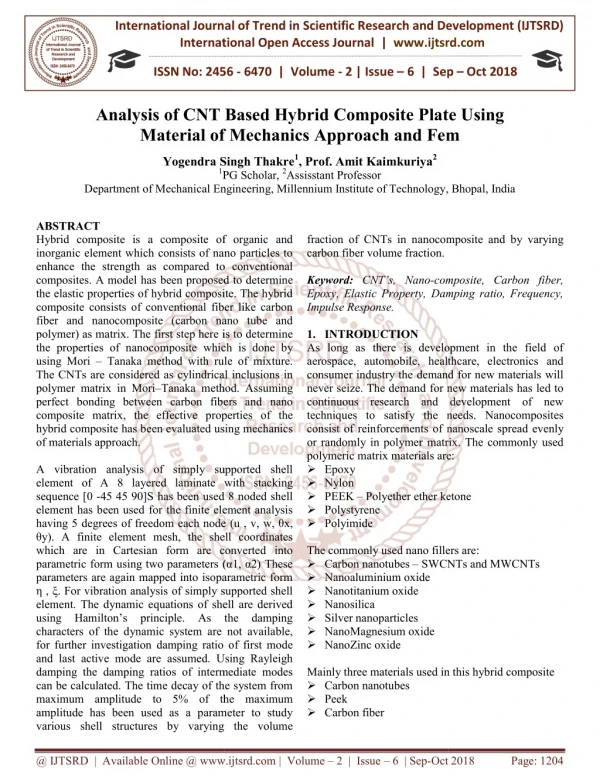
Hybrid composite is a composite which contains of nanoparticles to improve the strength as related to conventional composites. A model has been projected to define the elastic properties of hybrid composite. The hybrid composite contains of predictable fiber and nanocomposite as matrix. The first step here is to define the properties of nanocomposite which is done by using Mori Tanaka method. The CNTs are deliberated as cylindrical inclusions in polymer matrix in Mori Tanaka method. Arrogant perfect bonding among carbon fibers and nanocomposite matrix, the actual properties of the hybrid composite has been estimated using mechanics of materials approach. An 8 noded shell element has been used for the finite element analysis taking 5 degrees of free do mesh node u, v, w, x, y .A10 10 finite element mesh proceed sun remitting happening the convention of characteristic the shell element. The shell coordinates which are in Cartesian form are transformed into parametric formusing twoparameters 1, 2 . Theseparametersare over mapped into isoperimetric form , . A 16 layered enclose with stacking arrangement 0 454590 2S has been recycled for vibration investigation of simply supported shell element. The dynamic equations of shell are resultant using Hamilton's principle. As the damping types of the dynamic system are not available, for further analysis damping ratio of first mode and last active mode are presumed. Using Rayleigh damping the damping ratios of intermediate modes can be considered. The time decay of the structure from maximum amplitude to 5 of the maximum amplitude has been used as a parameter to study some shell structures by varying the volume fraction of CNTs in nanocomposite and by changing carbon fiber volume fraction. Anup Kumar Garg, | H. S. Sahu "Investigation of Nonlinear Damped Vibrations of a Hybrid Laminated Composite Plate Subjected to Blast Load" Published in International Journal of Trend in Scientific Research and Development (ijtsrd), ISSN: 2456-6470, Volume-3 | Issue-4 , June 2019, URL: https://www.ijtsrd.com/papers/ijtsrd24035.pdf Paper URL: https://www.ijtsrd.com/engineering/mechanical-engineering/24035/investigation-of-nonlinear-damped-vibrations-of-a-hybrid-laminated-composite-plate-subjected-to-blast-load/anup-kumar-garg<br>

E N D
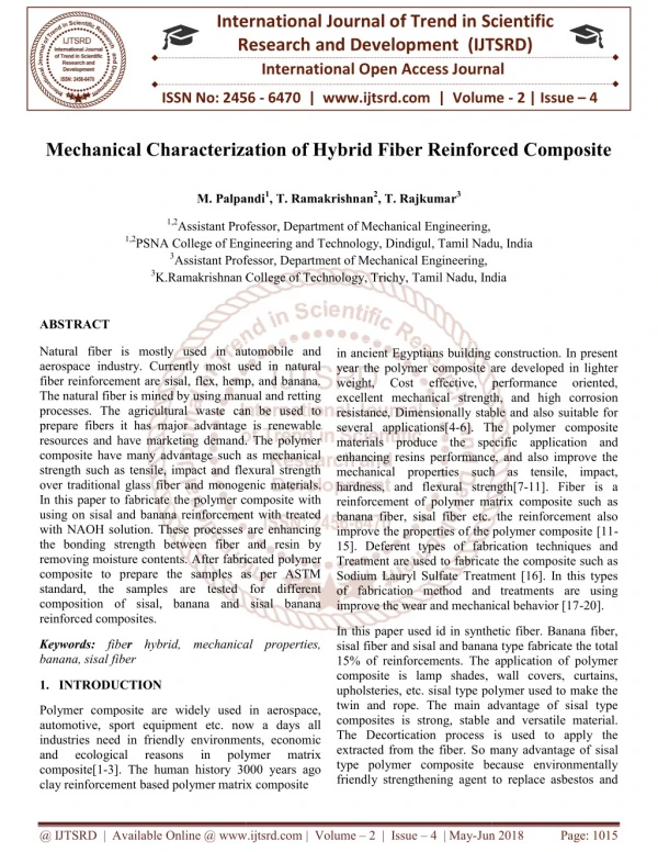
International Journal of Trend in Scientific Research and Development (IJTSRD) Volume: 3 | Issue: 4 | May-Jun 2019 Available Online: www.ijtsrd.com e-ISSN: 2456 - 6470 Investigation of Nonlinear Damped Vibrations of a Hybrid Laminated Composite Plate Subjected to Blast Load Anup Kumar Garg, H. S. Sahu Department of Mechanical Engineering, Millennium Institute of Technology, Bhopal, Madhya Pradesh, India How to cite this paper: Anup Kumar Garg, | H. S. Sahu "Investigation of Nonlinear Damped Vibrations of a Hybrid Laminated Composite Plate Subjected to Blast Load" Published in International Journal of Trend in Scientific Research and Development (ijtsrd), ISSN: 2456- 6470, Volume-3 | Issue-4, June 2019, pp.1077-1081, URL: https://www.ijtsrd. com/papers/ijtsrd2 4035.pdf Copyright © 2019 by author(s) and International Journal of Trend in Scientific Research and Development Journal. This is an Open Access article distributed under the terms of the Creative Commons Attribution License (CC BY 4.0) (http://creativecommons.org/licenses/ by/4.0) I. INTRODUCTION Vibration needs to be reduced in most of the rotor-shaft system so that an effective functioning of the rotating machines is attained. Almost all rotating parts should be vibration free as it sources a lot of problems leading to instability of the system. Therefore there is a necessity to reduce the vibration level in rotating bodies for proper functioning of the system and different researchers are aiming for this. In the present days, composite materials are commonly used for the manufacturing of rotor .It is because composites have light weight, high strength, high damping capacity. Weight of the composite materials is less because long stiff fibers are surrounded in very soft matrix. Composites are made by at least two materials at macroscopic level. This type of unique reinforcement gives a lot of improvement for different applications. Fiber reinforced polymer (FRP) composite is a polymer matrix now which the reinforcement is fiber. The reinforcement of fiber can be done either by continuous fiber or by intermittent ABSTRACT Hybrid composite is a composite which contains of nanoparticles to improve the strength as related to conventional composites. A model has been projected to define the elastic properties of hybrid composite. The hybrid composite contains of predictable fiber and nanocomposite as matrix. The first step here is to define the properties of nanocomposite which is done by using Mori – Tanaka method. The CNTs are deliberated as cylindrical inclusions in polymer matrix in Mori – Tanaka method. Arrogant perfect bonding among carbon fibers and nanocomposite matrix, the actual properties of the hybrid composite has been estimated using mechanics of materials approach. An 8 noded shell element has been used for the finite element analysis taking 5 degrees of free do mesh node (u, v, w,θx,θy).A10×10 finite element mesh proceed sun remitting happening the convention of characteristic the shell element. The shell coordinates which are in Cartesian form are transformed twoparameters(α1, α2). Theseparametersare over mapped into isoperimetric form(η,ξ). A 16 layered enclose with stacking arrangement [0-454590]2S has been recycled for vibration investigation of simply supported shell element. The dynamic equations of shell are resultant using Hamilton’s principle. As the damping types of the dynamic system are not available, for further analysis damping ratio of first mode and last active mode are presumed. Using Rayleigh damping the damping ratios of intermediate modes can be considered. The time decay of the structure from maximum amplitude to 5% of the maximum amplitude has been used as a parameter to study some shell structures by varying the volume fraction of CNTs in nanocomposite and by changing carbon fiber volume fraction. Keywords: Keywords: Carbon nanotubes, Single walled carbon nanotube, Double walled carbon nanotubes, Multi walled carbon nanotubes IJTSRD24035 parametric formusing into fiber. Active materials like magneto-strictive material, electromagnetic actuator and micro fiber carbon are also used for the vibration control of rotating parts. Piezoelectric material property to improve charge when mechanically stressed is utilized to bring control of vibration in moving parts. It is used as actuator as well as sensor in the system. Magnetostictive materials are like ferromagnetic material. Materials like cobalt, nickel and iron are magnetostictive materials and therefore change in the shape and size occurs when they are magnetized. Electromagnetic actuator is used very often as it gains the magnetic property when its coils are provided with current and the displaced position of the rotor can be attuned according to the current supply. A sensor measures the displacement of the rotor from its reference position, a microcontroller as a controller derives a control signal from the measures and gives signal to a power amplifier into a control current, and the control current generates the piezoelectric material, @ IJTSRD | Unique Paper ID - IJTSRD24035 | Volume – 3 | Issue – 4 | May-Jun 2019 Page: 1077
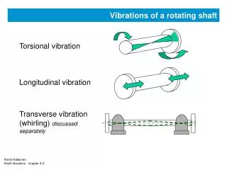
International Journal of Trend in Scientific Research and Development (IJTSRD) @ www.ijtsrd.com eISSN: 2456-6470 magnetic forces within the actuating magnet in such away that the rotor remain sin its hovering position. This enables very high rotational speed to be realized. Active magnetic bearing is free of lubricant, which avoids servicing and also enables use in clean room environment. Maintenance is also decreased due to absence of surface wear, so that as long as the control system functions as intended, there could be no maintenance. One major disadvantage to using magnetic bearing sis their complexity. A very knowledgeable person in the field is generally required to design and implement a successful system. Because of the large amount of effort and time required for development and the increase in the number of components, compared to a traditional bearing, the initial costs are much higher. However, depending on the application, the return on investment for these initial costs could be relatively short for a system, for example, that runs with a much higher efficiency due to the lack of bearing friction resistance.[1]. II. Literature Review Raifee et al [7] estimated mechanical properties of epoxy based nanocomposite with SWCNT, MWCNT and graphene platelets were compared for weight fractions of 0.1%. The material properties measured were Young’s modulus, fracture toughness, ultimate tensile strength. The tensile strength of graphene based nanocomposites showed better properties as compared to CNT based nanocomposites. F. H. Gojny et al [8] detected mechanical properties resulted in an increase in Young’s modulus, strength at weight fractions of 0.1%. There was good agreement between experimental observed data and results from modified Halpin-Tsai relation. Florian H [9] proposed choosing appropriate type of CNTs (SWCNTs or DWCNTs or MWCNTs) has been a problem ever since they are being used in composites. They evaluated the properties of nanocomposite for different nano fillers. The nanocomposites exhibited greater strength, stiffness and fracture toughness. They found that DWCNT based nano composite displayed greater fracture toughness. Seidel et al [10] estimated actual elastic properties of composites consisting of aligned SWCNTs or MWCNTs using Mori-Tanaka method. The effects of an inter phase layer between CNTs and the polymer is also investigated using a multi-layer composite cylinders approach. Liu and Chen [11] estimated effective elastic properties of the nanocomposite are evaluated using continuum modeling and finite element method. The extended rule of mixture is used to definethe properties of the continuum model. III. Finite Element Formulation The shell geometry used in the present formulation has been developed using an orthogonal curvilinear coordinate system with the mid-plane of the shell assumed to be the reference surface as shown in Fig.4.1. The shell mid-surface in the Cartesian rectangular coordinate system has been first mapped into a parametric domain through the suitable exact parameterization. Two liberated coordinates (α1,α2) in the parametric space have been measured as the mid-surface rounded coordinates of the shell. The normal direction coordinate to the middle surface of the shell has been represented by z. The reference surface or the shell mid- surface can be described in the global Cartesian coordinates in terms of the position vectoras, Figure1.Geometry of Shell Structure In Cartesiancoordinates IV. Hybrid composite is a composite which consists of nanoparticles to develop the strength as related to conventional composites. A model has been proposed to define the elastic properties of hybrid composite. The hybrid composite contains of conventional fiber and nanocomposite as matrix. The first step here is to define the properties of nanocomposite which is done by using Mori – Tanaka method. The CNTs are measured as cylindrical inclusions in polymer matrix in Mori – Tanaka method. Assuming flawless bonding among carbon fibers and nanocomposite matrix, the active properties of the hybrid composite has been estimated using mechanics of materials approach. An 8 noded shell component has been used for the finite element analysis having 5 degrees of freedom each node(u, v, w,θx ,θy ). A 10×10 finite element mesh takes been support to just right the shell section. The shell coordinates which are in Cartesian form are transformed into parametric form using two parameters (α1,α2) These parameters are over recorded into is oparametric form(η,ξ). A16 layereden close with stacking sequence [0 -45 45 90]2S has been used for vibration analysis of simply supported shell component. The dynamic equations of shell are resultant using Hamilton’s principle. As the damping types of the dynamic system are not available, for additional analysis damping ratio of first mode and last active mode are assumed. Using Rayleigh damping the damping ratios of intermediate modes can be considered. The time decay of the system from maximum amplitude to 5% of the maximum amplitude has been used as a stricture to reading various shell structures by varying the volume fraction of CNTs in nanocomposite and by changing carbon fiber volume fraction. ?Validation of formulation Free vibration analysis is done to certify the above formulation. A 2, 3 and 4 layered cross ply laminate has been used to carry out free vibration analysis by varying the a/h ratio and R/a ratio of the spherical shell. Resultsand Discussion @ IJTSRD | Unique Paper ID - IJTSRD24035 | Volume – 3 | Issue – 4 | May-Jun 2019 Page: 1078
International Journal of Trend in Scientific Research and Development (IJTSRD) @ www.ijtsrd.com eISSN: 2456-6470 TABLE 1 NON-DIMENSIONAL FREQUENCY[REF:23] 1 2 5 14.481 10.749 9.2302 8.9841 8.9212 8.9035 8.9009 8.9001 100 125.93 67.369 28.826 16.706 11.841 10.063 9.7825 9.6873 10 16.115 13.382 12.372 12.215 12.176 12.165 12.163 12.162 100 125.99 68.075 30.993 20.347 16.627 15.424 15.244 15.183 10 16.172 13.447 12.437 12.280 12.240 12.229 12.228 12.226 0/90/90/0 100 126.33 68.294 31.079 Present Formulation a/h 1 2 5 10 15.51217 11.1521 8.906713 8.373873 8.166252 8.061078 8.027878 7.990367 100 136.0635 73.90925 31.89584 18.20593 12.12838 9.353029 10 15.5545 12.22585 11.01655 10.82998 10.78238 10.76802 100 142.7383 76.47821 32.7317 19.15716 13.78834 11.85253 11.54031 11.43834 0/90/90/0 10 14.8861 11.99612 10.95903 10.79977 10.75936 10.74652 10.74316 10.73102 0/90/90/0 100 134.838 72.67357 31.29011 18.50931 13.52047 11.74193 11.45988 11.35508 Material Properties Constituet C11(GPa) C12(GPa) C22(GPa) C23(GPa) C55(GPa) Density(kg/m3) Carbon fiber 236.4 10.6 (25,25),5 Walled CNT[6] 1180 146 Epoxy[18] 13.4615 5.7692 13.4615 Panel 0/90 0/90 0/90/0 0/90/0 0/90/90/0 a/h 10 R/a 10 20 50 100 500 20.38 16.638 15.426 15.245 15.184 Panel 0/90 0/90 0/90/0 0/90/0 R/a 10 20 50 100 500 8.72118 10.7647 8.358714 10.75471 24.8 411 10.7 133 5.7692 25 189 3.8462 1800[2] 1740[2] 1150 ?C11 Figure 4 Variation of C23w.R.Tvariation of Carbon Fiber and Cnt Volumefraction From Fig. 3 and Fig.4, similarly as C11, the elastic properties along 1-2 direction also increase with the increase with in volume fraction of carbon fiber. At lower volume fractions (10%) it can be observed that CFRP has elastic modulus of 6Gpa, but with increase in CNT volume fraction from 1% to 5%, the elastic properties have increased from 6.8Gpa to 10Gpa. With the increase in carbon fiber volume fraction, it can be observed that composites having lower CNT volume fractions show steep increase in elastic properties than compared to composites having higher CNT volume fractions. Figure 2variation of C11 w.r.t variation of carbon fiber and cntvolumefraction From Fig.2, it can be seen that as the carbon fiber volume fraction increases the longitudinal elastic properties rise. At lower volume fractions of carbon fiber (10%) it can be observed that for CFRP composite the elastic modulus is around 35GPa, but with the increase in volume fraction of CNT from 1% to 5% the elastic modulus has improved from 38GPa to 47.3GPa. With the increase in carbon fiber volume fraction, the volume fraction of nanocomposite goes on decreasing; as a result the elastic properties almost converge at higher volume fractions of carbon fiber. ?C12 and C23 Figure.3 variation of C12w.r.t variation of carbon fiber and cntvolumefraction Figure.5variation of C22 W.R.T Variation of Carbon Fiber and Cnt Volumefraction @ IJTSRD | Unique Paper ID - IJTSRD24035 | Volume – 3 | Issue – 4 | May-Jun 2019 Page: 1079
International Journal of Trend in Scientific Research and Development (IJTSRD) @ www.ijtsrd.com eISSN: 2456-6470 ?C22 From Fig. 5, it can be seen that the transverse elastic properties have improved with the addition of CNT in matrix material for lower volume fractions of carbon fiber. This increase in elastic properties can be attributed to the randomly distributed CNTs. With the increase in carbon fiber volume fraction the composites having lower volume fractions of CNT have shown an increase in transverse elastic modulus, but for composites having higher volume fractions of CNT with the increase in carbon fiber volume fraction around is decrease in transverse elasticmodulus. Figure.9 Decay Time for thick plate by varying the cntvolume fractionsfor different Figure.10 decay time for thin plate by vary in g the cnt volume fractions for different Fig. 9 and Fig. 10 expression the decay time for thick and thin plates. At lower volume fractions carbon fiber, the decay time of the structure goes on decreasing with increase in CNT volume fraction. As the volume fraction of carbon fiber increases the decay time similarly decreases. Conclusions The hybrid composite has been modeled using Mori-Tanaka method and procedure of materials method. It is found that The longitudinal properties C11 of the hybrid composite increase with the increase in volume fraction of CNT at lower volume fractions of carbon fiber. As the volume fraction of carbon fiber goes on increasing the longitudinal modulus tends to converge because the volume fraction of CNT goes on decreasing. There is tremendous increase in elastic properties C12 and C23 of the hybrid composite with the increase in volume fraction of CNT at lower volume fractions of carbon fiber. As the volume fractions of carbon fiber goes on increasing there is slow increase in composites having higher volume fractions of CNT as compared to composites having lower volume fractions of CNTs. Future Scope Estimate temperature dependent rmalproperties. Buckling analysis of hybrid composite covered shell structure. Active vibration control of the covered shell structure. Delamination analysis. Nonlinear analysis of laminated shell structure. REFERENCES [1]GauravKumar, “Design and Analysis of a Radial Active Magnetic Bearing for Vibration”, vol. 175(6), (2016). Figure.6 Variation of C55w.R.Tvariation of Carbonfiber and Cnt Volumefraction ?C55 From Fig. 6, it can be observed that the in-plane shear properties have increased with increase in volume fractions of CNT and carbon fiber. Composites normally fail due to shear. So in order avoid failure it is expedient to use hybrid composite in place of conventional CFRPcomposites. ?Impulse response Figure.7 impulse response of cfrpcomposite for thickplate and hydro the [2]Singh. S. P., Gupta. K. “Composite Shaft Rotor dynamic analysis using a layerwise theory”, Journal of Sound and Vibration, vol. 191(5), pp. 739-756,(2016). Figure.8 Impulse response of CFRP composite for Thinplate Fig. 5.6 and Fig. 5.7 indicate the retort of thick plate and thin plate in modal coordinates for the first mode of vibration. [3]Kim. W., Argento. A., and Scott. R. A “Free Vibration of a Rotating Tapered Composite Shaft System”, Journal of Sound and Vibration, vol. 226(1), pp. 125-147,(2015). @ IJTSRD | Unique Paper ID - IJTSRD24035 | Volume – 3 | Issue – 4 | May-Jun 2019 Page: 1080
International Journal of Trend in Scientific Research and Development (IJTSRD) @ www.ijtsrd.com eISSN: 2456-6470 [4]Chang. M. Y., Chen. J. K., and Chang. C. Y. “A simple Spinning Laminated International Journal of Solids and Structures, vol. 41, pp. 637-662,(2015). Mechanical HsingUniversity, Taiwan(2014).. Engineering, National Chung Composite Shaft Model”, [9]Nelson. F. C., “Rotor Dynamics without Equation”, Professor of Mechanical Engineering, Tuffts University, Medford, MA 02155,USA. (2013). [5]Ghoneam. S. M.,Hamada. A. A., and El-Elamy. M. I. “Dynamic Analysis of Composite Shaft”, Department of Production Engineering and Mechanical Design, Menoufia University, Egypt (2015). [10]Perini E. A., Bueno D. D., Santos R. B., Junior V. L., NascimentoLuiz de MachineryVibrationControlBasedonPolesAllocationusin gMagneticActuators”,International Engineering Optimization, Rio de Janeiro, Brazil, June (2013), pp.1 -5 P. “Rotating [6]Boukhalfa.A., “Dynamic Analysis of a Spinning Laminated Composite Shaft Using the hp- Version of the Finite Element Method”, Department of Mechanical Engineering, University of Tlemcen, Algeria (2014). Conference on [11]Bennett, engineering”,(2012). Stuart “A history of control [7]Richardet. G. J., Chatelet. E., and Baranger. T. N. “Rotating Internal Damping in the Case of Composite Shaft”, University de Lyan, CNRS, INSA-Lyan, LaMCoS UMR5259, VelleurbanneF-69621,France(2014). [12]Ang K. H., Chong G.C.Y., and Li Y. “PID control system analysis, design, and technology”, IEEE Trans Control Systems Tech, vol.13, no.4, (2012),pp.559-576. [8]Chang. M. Y., Chen. J. K., Chang. C. Y., “A simple spinning laminated composite shaft model”, Department of [13]Foeppl A., Der Civilingenieur, “Das Problem der Delaval‟schenTurbinenvelle” (2012). @ IJTSRD | Unique Paper ID - IJTSRD24035 | Volume – 3 | Issue – 4 | May-Jun 2019 Page: 1081