Download
1 / 6
60 likes | 67 Views
Myanmar has natural gifts of hydropower resources and most of area are a great distance far from national grid syatem. To develop throughout the country of courses, needs to fulfil the electricity requirements for cities as well as country sides or villages. Consequently, Micro hydropower is cost effective, environmentally friendly and manufactured locally. This research has studied on the hydropower generating system and mainly emphasized on the design of synchronous generator for used in Micro hydropower project Loi Unn village . In this paper, fixed blade axial flow propeller turbine is suiTABLEfor this Mico hydropower project and the design data of 1 phase, 6 pole, 1000 r.p.m, 50 Hz, 3 kVA synchronous generator is mentioned. The calculated results are checked based on the design limits and these are regarded as appropriate values. Seng Ram | Dr. Zar Kyi Win "Design and Calculation of Synchronous Generator used in Micro Hydropower Project (Loi Unn Village)" Published in International Journal of Trend in Scientific Research and Development (ijtsrd), ISSN: 2456-6470, Volume-4 | Issue-3 , April 2020, URL: https://www.ijtsrd.com/papers/ijtsrd30630.pdf Paper Url :https://www.ijtsrd.com/engineering/electrical-engineering/30630/design-and-calculation-of-synchronous-generator-used-in-micro-hydropower-project-loi-unn-village/seng-ram<br>

E N D
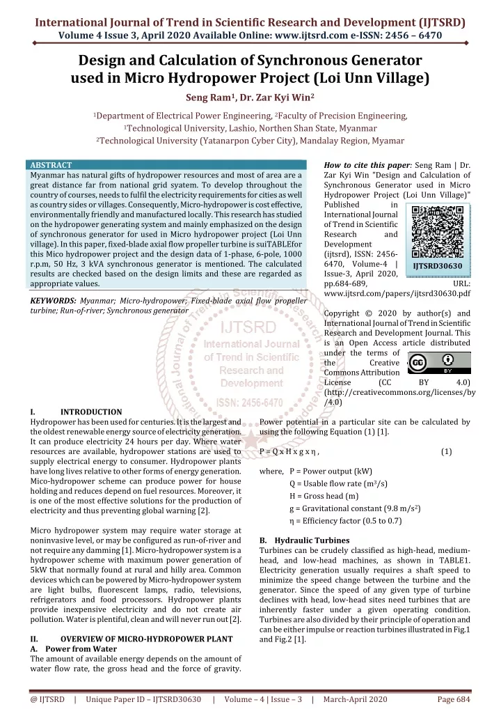
International Journal of Trend in Scientific Research and Development (IJTSRD) Volume 4 Issue 3, April 2020 Available Online: www.ijtsrd.com e-ISSN: 2456 – 6470 Design and Calculation of Synchronous Generator used in Micro Hydropower Project (Loi Unn Village) Seng Ram1, Dr. Zar Kyi Win2 1Department of Electrical Power Engineering, 2Faculty of Precision Engineering, 1Technological University, Lashio, Northen Shan State, Myanmar 2Technological University (Yatanarpon Cyber City), Mandalay Region, Myamar ABSTRACT Myanmar has natural gifts of hydropower resources and most of area are a great distance far from national grid syatem. To develop throughout the country of courses, needs to fulfil the electricity requirements for cities as well as country sides or villages. Consequently, Micro-hydropower is cost effective, environmentally friendly and manufactured locally. This research has studied on the hydropower generating system and mainly emphasized on the design of synchronous generator for used in Micro hydropower project (Loi Unn village). In this paper, fixed-blade axial flow propeller turbine is suiTABLEfor this Mico hydropower project and the design data of 1-phase, 6-pole, 1000 r.p.m, 50 Hz, 3 kVA synchronous generator is mentioned. The calculated results are checked based on the design limits and these are regarded as appropriate values. KEYWORDS: Myanmar; Micro-hydropower; Fixed-blade axial flow propeller turbine; Run-of-river; Synchronous generator How to cite this paper: Seng Ram | Dr. Zar Kyi Win "Design and Calculation of Synchronous Generator used in Micro Hydropower Project (Loi Unn Village)" Published in International Journal of Trend in Scientific Research and Development (ijtsrd), ISSN: 2456- 6470, Volume-4 | Issue-3, April 2020, pp.684-689, www.ijtsrd.com/papers/ijtsrd30630.pdf Copyright © 2020 by author(s) and International Journal of Trend in Scientific Research and Development Journal. This is an Open Access article distributed under the terms of the Creative Commons Attribution License (CC (http://creativecommons.org/licenses/by /4.0) IJTSRD30630 URL: BY 4.0) I. Hydropower has been used for centuries. It is the largest and the oldest renewable energy source of electricity generation. It can produce electricity 24 hours per day. Where water resources are available, hydropower stations are used to supply electrical energy to consumer. Hydropower plants have long lives relative to other forms of energy generation. Mico-hydropower scheme can produce power for house holding and reduces depend on fuel resources. Moreover, it is one of the most effective solutions for the production of electricity and thus preventing global warning [2]. Micro hydropower system may require water storage at noninvasive level, or may be configured as run-of-river and not require any damming [1]. Micro-hydropower system is a hydropower scheme with maximum power generation of 5kW that normally found at rural and hilly area. Common devices which can be powered by Micro-hydropower system are light bulbs, fluorescent lamps, radio, televisions, refrigerators and food processors. Hydropower plants provide inexpensive electricity and do not create air pollution. Water is plentiful, clean and will never run out [2]. II. OVERVIEW OF MICRO-HYDROPOWER PLANT A.Power from Water The amount of available energy depends on the amount of water flow rate, the gross head and the force of gravity. INTRODUCTION Power potential in a particular site can be calculated by using the following Equation (1) [1]. P = Q x H x g x η , where, P = Power output (kW) Q = Usable flow rate (m3/s) H = Gross head (m) g = Gravitational constant (9.8 m/s2) η = Efficiency factor (0.5 to 0.7) B.Hydraulic Turbines Turbines can be crudely classified as high-head, medium- head, and low-head machines, as shown in TABLE1. Electricity generation usually requires a shaft speed to minimize the speed change between the turbine and the generator. Since the speed of any given type of turbine declines with head, low-head sites need turbines that are inherently faster under a given operating condition. Turbines are also divided by their principle of operation and can be either impulse or reaction turbines illustrated in Fig.1 and Fig.2 [1]. (1) @ IJTSRD | Unique Paper ID – IJTSRD30630 | Volume – 4 | Issue – 3 | March-April 2020 Page 684
International Journal of Trend in Scientific Research and Development (IJTSRD) @ www.ijtsrd.com eISSN: 2456-6470 1.Synchronous generator and 2.Induction generator 3.Criteria for selection of generators are: 4.Maximum turbine power 5.Run away speed of turbine 6.Horizontal or vertical construction 7.Whether isolated or parallel operation 8.Constant load or variable load 9.Availability of grid supply 10.Reactive power supply Synchronous generators are standard in electrical power generation and are used in most power plants. Asynchronous generators are more commonly known as induction generators. Both of these generators are available in three-phase or single-phase systems. And, both machines may have the same stator design but different rotor design as illustrated in Fig.4 and Fig.5. The rotor is a rotating part of a machine. There are two types of the rotor; salient pole type and cylinder rotor type or non-salient pole rotor type as shown in Fig.3. System capacity, type of load and length of the transmission/ distribution net-work dictate whether a single- or threephase generator should be used [11]. Selection of the generators based on size of scheme and different between poles and speed are shown in TABLE3 and TABLE4[1]. TABLE3. SELECTION OF GENERATOR Size of Scheme Type of Generator and Phase threephase TABLE4. DIFFERENT BETWEEN POLES AND SPEED Number of poles rpm for 50 Hz rpm for 50 Hz 2 3000 4 1500 6 1000 8 750 10 600 12 500 14 429 16 375 18 333 20 300 40 150 Full load load efficiencies of synchronous generators vary from 75 to 90 percent, depending on the size of the generator. Efficiency of induction generator is approximately 75 percent at full load and decreases to as low as 65 percent at part load [11]. If high portions of loads are likely to be inductive loads, such as motor and fluorescent lamps, a synchronous generator is better than an induction generator. Induction generators in standalone application mode cannot supply the high-surge power required by motor loads during start up [1]. TABLE1. TURBINE TYPES BASED ON HEADS Turbine Runner (>50m) Pelton Turgo Multi-jet Pelton High-Head Midium-Head (10-50m) Crossflow Turgo Multi-jet Pelton Francis PAT Low-Head (<10m) Impulse Crossflow Properller Kaplan Reaction (a) (b) (c) (d) Fig.1. Groups of Impulse Turbine: A. Single-Jet Pelton B. Multi-Jet Pelton C. Turgo D. Crossflow More than 25 kW Up to 10 kW 10 to 25 kW Fig.2. Groups of reaction turbine: A. Properl B. Kaplan C. Francis Typical efficiency ranges of turbines are given in TABLE2. Turbines are chosen or are sometimes tail or made according to site conditions. Selecting the right turbine is one of the most important parts of designing a hydroelectric system, and the skills of an engineer are needed in order to choose the effective turbine for a site, taking into consideration cost, variations in head, flow, and the amount of sediment in the water and overall reliability of the turbine [11]. TABLE2. EFFICIENCY RANGE OF TURBINES Turbine Type Impulse turbines: Pelton Turgo Crossflow Reaction turbines: Francis PAT Propeller Kaplan C.Hydroelectric Generator Electrical power can be generated in either AC or DC. AC has the advantage of allowing the use of common household appliances and tools and is much more economical for transmitting power to consumers. Thus, AC system is considered in this study [3]. There are two main types of an AC generator which are used in hydro-electric scheme. They are: Induction or Synchronous, Single or Induction or Synchronous, Three-phase Synchronous, Three-phase 3600 1800 1200 900 720 600 514 450 400 360 180 Efficiency Range 80-90% 80-95% 65-85% 80-90% 60-90% 80-95% 80-90% Fig.3.Types of Rotors @ IJTSRD | Unique Paper ID – IJTSRD30630 | Volume – 4 | Issue – 3 | March-April 2020 Page 685
International Journal of Trend in Scientific Research and Development (IJTSRD) @ www.ijtsrd.com eISSN: 2456-6470 There are about 140 houses in Loi Unn village and its population is about 1000.The location of this village is very far from the national grid system and the natural resource for micro-hydropower is existed in this area. So, the hydropower plants are constructed in Loi Unn village. Moreover, it is already avoided the uneconomical transmission system and diesel-electric generation system in that village. Micro-hydropower plants can be installed at three possible locations, they are: waterfall, small-dam and site-channel. In this study, hydropower plants are installed at a concrete small-dam which is constructed across the Loi Unn stream as mentioned in the following Fig.7 and Fig.8. (a) (b) Fig.4. Types of Rotor Constrtuction A.Salient pole rotor B.Cylindrical-pole rotor (Non salient pole) Fig.7. Turbine -generator set (Before Inatallation) (a) (b) Fig.5. Different Rotor Design A.Salient-pole rotor B.Cylindrical-pole rotors By using synchronous generator, there is no affection against grid when parallel running. On the other hand, big over- current will rush and voltage drop of grid will occur if induction generator is applied [5]. III. MICRO-HYDROPOWER PROJECT (LOI UNN) The resource of the micro-hydropower is existed at Loi Unn stream which is located near Loi Unn village which is 0.8 km far from Kut Kai town in Northern Shan State, Myanmar. Loi Unn stream is shown in Fig .6. Fig.8. Loi Unn Micro-Hydropower Project Total number of turbine-generator sets which are installed at Loi Unn stream is seven. The capacity of each synchronous generator is 3kVA. The turbine-generator set is installed in the concrete spiral casing as shown in the following Fig .9. Fig.9. Top View of Generator in Spiral casing The type of each turbine is fixed-blade, axial flow, propeller type which is included in the group of reaction turbine. The 4-blade propeller runner of Loi Unn project is mentioned in the following Fig .10. Fig.6. Loi Unn Stream @ IJTSRD | Unique Paper ID – IJTSRD30630 | Volume – 4 | Issue – 3 | March-April 2020 Page 686
International Journal of Trend in Scientific Research and Development (IJTSRD) @ www.ijtsrd.com eISSN: 2456-6470 IV. The main parts construction of the 6-pole, synchronous generator is mentioned in Fig.12. It consists of stator, rotor and losses. Design of stator has main dimension of stator frame, stator winding and depth of stator core. Design of rotor has axial length of pole, width of pole, high of pole, air-gap length and outer diameter of the rotor. Losses consist of total losses of stator winding, total iron losses, total field copper losses, exciter losses and friction and windage losses [5]. DESIGN THEORY OF SYNCHRONOUS GENERATOR Fig .10. Propeller Runner of Loi Unn Project The rated speed of the propeller runner is 1000 r.p.m. According to the theory of synchronous generator, the number of poles of generator is six-poles. The stator and salient pole rotor of synchronous generator of Loi Unn project is shown in Fig .11. The runner of propellers turbine and the rotor of synchronous generator can be connected with the same shaft because the speed of two machines are matched. Fig.12. Main parts of 6-pole synchronous generator A.Main Dimension of Stator Frame Internal diameter and gross length of the stator frame are its main dimensions. The output equation is the basic tool to initiate the design of synchronous machine, which relates the output of the machine with the main dimensions of the stator [11]. Output of 1-phase synchronous machine, Q = Kʹ D2Lns, where, D - Internal Diameter of the Stator L - Gross Length of Stator Core Output coefficient of 1-phase synchronous machine, Kʹ = (11/3) Bav q Kw 10-3 where, Bav - Specific Magnetic Loading q - Specific Electric Loading Kw - Winding Factor For rectangular poles, the ratio of axial length of the core to pole pitch varies from 0.8 to 3. A suiTABLEratio may be assumed for axial length to pole pitch depending upon the design specifications [5]. L / τP = 0.8 to 3 Air-gap length, lg = (0.012 to 0.016) × pole pitch B.Design of Stator Winding Air-gap flux per pole, φ = Bav τP L Number of stators turns per phase, Tph = Eph / (4.44 f φ Kw) Slot pitch τS = πD / number of stator slots (2) Fig.11. Six-Poles Synchronous Generator The electrical power generated from seven Mico- hydropower plants are transmitted to seven houses which are located at the load-center of Loi Unn village. Voltage- drop problem is overcome by using 3kVA autotransformer at these seven houses. Then, the electrical power is sub- transmitted to other houses from these seven houses. Some specifications of Loi Unn micro-hydropower project is mentioned in the following TABLE5. TABLE5. SPECIFICATIONS OF MICRO-HYDROPOWER PROJECT (LOI UNN VILLAGE) (3) Fixed-blade axial flow propeller 4 3 m 0.16 m3/s Direct-coupled Salient pole synchronous 3 kVA Single-phase A.C 1000 r.p.m 6 0.8 50 Hz 230 V Turbine type (4) No. of turbine blade Head (h) Flow rate (q) Generator drive system Generator type Generator capacity Sypply system Rated speed No.of poles of generator Power factor Frequency Voltage (5) (6) (7) (8) @ IJTSRD | Unique Paper ID – IJTSRD30630 | Volume – 4 | Issue – 3 | March-April 2020 Page 687
International Journal of Trend in Scientific Research and Development (IJTSRD) @ www.ijtsrd.com eISSN: 2456-6470 Conductors per slot, ZS = 2 Tph / number of stator slots Cross-sectional area of the conductor, aS = Full-load current / Current density Number of stator teeth per pole arc, Nt = Pole arc / τS Width of stator tooth at air gap surface, bt = φ / (Bt Lic Nt) , where, Bt - flux density in the stator tooth Lic - net iron length of stator core Width of the stator slot, bs = τS - bt Mean length of the stator winding, Lmt = 2L + 2.5τP + 0.05 kV + 0.15 Resistance of the stator winding, Rs = ρ Lmt Tph/ aS Copper losses of stator winding, Pcus = Iph2 Rph Eddy current losses in the stator winding, Peds = (Kdav - 1) Pcus where, Kdav = average loss factor Total losses of the stator winding, Pts = Pcus + Peds + Pss where, Pss = stay load losses Effective resistance of the stator winding, Resistance drop = Iph Rph Kdav Depth of stator core, dc = φc/ Bc Lic Outer diameter of the stator core, Do = D + 2hc + 2dc C.Design of Rotor Air gap length, Lg = ATg / 0.796 Bg Kg 106 Rotor diameter, Dr = D - 2Lg Width of the pole, bp = Ap / Lp where Lp = axial length of the pole Heigh of the pole, hF = D.Regulation Area of conductor, (9) Vc = (28) (10) Resistance of field winding, RF = (29) (11) Copper losses in the field winding, Pcu,loss = If2 Rf Total losses in all the coil, Ptotal,cu = Pcu,loss pole Total field copper losses, Pt,f = Pcu,loss + Ptotal,cu Friction and windage losses = 1% of output Efficiency, (30) (12) (31) (32) (13) (33) (14) η = (34) (15) V. The calculated results of the designed generator are mentioned in the following TABLE6 to TABLE9. TABLE6. MAIN DIMENSIONS Specification Full load output Line voltage Number of Phase Frequency Speed Number of poles Output coefficient Internal diameter of stator D Gross length of stator Peripheral speed TABLE7. STATOR DESIGN Specification Symbol Unit Flux per phase φ Turns per phase Tph Conductor per slot ZS Number of slots Zs Conductor c.s.a as Size of conductor - Width of slot bs Width of stator tooth bt Teeth per pole arc Nt Depth of slot hs Winding Type - Resistance of winding Rph Effective resistance - Effective reactance - CALCULATED RESULTS (16) (17) Symbol Q V - f N p Kʹ Unit kVA Volts 230 - Hz rpm - - m m m/s Value 3 1 50 1000 6 25.282 0.26 0.11 13.6136 (18) (19) (20) L v (21) Value Wb - - - mm2 4.33 mm 10 × 0.3 m 0.016 m 0.018 - 2.8 m 0.0116 - Double layer, Lap Ω 0.277 p.u 0.016 p.u 0.04 5.69 ×10⁻³ 190.64 16 24 (22) (23) (24) (25) Cross-sectional area of the rotor core, Ac = 0.5 φp / Bc Depth of rotor core, dc = Ac/ Lc (26) (27) @ IJTSRD | Unique Paper ID – IJTSRD30630 | Volume – 4 | Issue – 3 | March-April 2020 Page 688
International Journal of Trend in Scientific Research and Development (IJTSRD) @ www.ijtsrd.com eISSN: 2456-6470 TABLE8. ROTOR DESING Specification Rotor diagram Air-gap length Axial length of pole Width of pole Height of pole Short circuit ratio Total no load ampere turns Full load field ampere turns Sectional area of field conductor af Field current Field turns per coil Resistance of field winding TABLE9. LOSSES AND EFFICIENCY Specification Exciter loss Copper losses in stator winding Eddy current losses in conductors Stray load losses Iron losses Rotor copper losses Friction & windage losses Total full load losses Efficiency VI. CONCLUSION Today, rural electrification plays an important role in rural development. Myanmar has high potential of hydropower resources. According to the following reasons, rural electrification recognized as key to rural development. Therefore, micro-hydropower system is installed at Loi Unn stream in order to fulfil the requirements of electrical power of villagers. This paper mentions the design data of Loi Unn Micro- hydropower project. 1-phase, 6 pole, 1000 r.p.m, 50 Hz, 3 kVA synchronous generator. Choice of the suiTABLE values of specific magnetic loading and specific electric loading are important. Since the designed generator is salient pole machine, the internal diameter of the stator is larger than the axial length of the stator core. The length of air gap in synchronous machines is also an important design parameter. Moreover, the number of stator slots should be properly chosen, as if affects the cost and the performance of synchronous machine. The flux density in the stator tooth at the gap surface should not exceed 1.8 Tesla for alternators. Otherwise, the tooth losses will be excessive. Furthermore, the choice of the proper value of the current density is also important. The high current density can be chosen for economical consideration. But, the resistance of the stator winding increases, resulting in higher copper loses in the stator winding, thus reducing the efficiency of the machine. Usual values for the current density in the stator winding can be assumed varying from 3 to 5 A/mm2. ACKNOWLEDGEMENT The author is deeply gratitude to Dr. Tin San, Pro-Rector of Technological University (Lashio) for his instruction. The author would like to express grateful thanks to her supervisor Dr. Zar Kyi Win, Faculty of Precision Engineering, Technological University (Yatanarpon Cyber City), Mandalay Region, Myamar for her valuable suggestions and supervision through this research work. REFRENCES [1] Dr. Aung Ze Ya “Pico-Hydropower system for Rural Electrification” in Proceedings of the ICSE 2009 December 2009, Yangon, Myanmar. Symbol Unit Value Dr m Lg m Lp m bp m hp m SCR - AT AT ATfl AT mm2 0.266 If A Tf - Rf Ω 0.26 0.0015 0.1 0.049 0.0943 0.9 881 1120 0.798 1404 18 [2] U Aung Ze Ya “Design, Construction and Testing of Generator for Hydropower Plant” in Proceedings of the CAFEO 22, December, 2004, Yangon, Myanmar. Symbol Unit - Value [3] Maung Aung Ze Ya “Design and Construction of Micro Hydropower Plant” M.E. thesis, Department of Electrical Power Engineering, Mandalay Technological University, Mandalay, Myanmar, Feb, 2002. W 8 Pcus W 46.77 0.9354 × 10⁻³ 7.02 106 71 24 254 91 Peds W [4] Luo Gaorong, Small Hydro Power in China- Experience and Technology, Hangzhou, China: Hangzhou Regional Centre, 1996. Ps - - - - η W W W W W % [5] Maung Aung Ze Ya “Design and Construction of MiniHydropower Plant” Ph.D. thesis, Department of Electrical Power Engineering, Yangon Tecnological university, Yangon, Myanmar, Dec, 2004. [6] A. Harvey, et al.., Micro-Hydro Design Manual, London, England: IT Publications Ltd, 1993. [7] Abdeen Mustafa Omer “Energy consumption, development and sustainability in Sudan” Sudan Engineering Society Journal, vol.52, pp.35-43, September, 2006. [8] Seng Ram, Dr. Zar Kyi Win and Dr. Aung Ze Ya “Analysis of Parallel Micro-Hydropower Generation for Rural Electrification (Loi Unn Village)” In Proceedings of National Conference on Science and Engineering, Mandalay, Northern Myanmar, (21-22 October, 2010) [9] P. K. Nag, Power Plant Engineering, 2nd ed., New Delhi, India: Tata McGraw-Hill Publishing Company Limited, 2006. [10] British Hydropower Association, A Guide to UK Mini- Hydro Developments, London, England: BHA, 2005. [11] Natural Resources Canada, Micro-Hydropower Systems, Canada: Natural Resources Canada, 2004. [12] Mittle V N. and Mittal A.2000.“Design of Electrical Machines”. Standard Pub lis ers Distributors. Deli India. [13] R. L. Daughherty, Hydraulic Turbines, 3rd ed., New York, USA: McGraw-Hill Book Company, 1920. [14] A. T. Sayers, Hydraulic and Compressible Flow Turbomachines, McGraw-Hill International Editions, Singapore: McGraw-Hill Book Company, 1992 @ IJTSRD | Unique Paper ID – IJTSRD30630 | Volume – 4 | Issue – 3 | March-April 2020 Page 689


![Micro Generator [ 가정용 소형발전시스템 ]](https://cdn3.slideserve.com/5639250/micro-generator-dt.jpg)