Download
1 / 69
700 likes | 839 Views
Mehmet Can Vuran, Instructor University of Nebraska-Lincoln. CSCE 230, Fall 2013 Chapter 8 Memory Hierarchy. Acknowledgement: Overheads adapted from those provided by the authors of the textbook. Genesis *.

E N D
Mehmet Can Vuran, Instructor University of Nebraska-Lincoln CSCE 230, Fall 2013Chapter 8Memory Hierarchy Acknowledgement: Overheads adapted from those provided by the authors of the textbook
Genesis* • Increasing gap between processor and main memory speeds since the 1980s, became the cause of primary bottleneck in overall system performance. • in the decade of 1990s, processor clock rates increased at 40%/year, while main memory (DRAM) speeds went up by only 11%/year. • Building small fast cache memories emerged as a solution. Effectiveness illustrated by experimental studies: • 1.6x improvement in the performance of VAX 11/780 (c. 1970s) vs. 15x improvement in performance of HP9000/735 (c. early 1990s) [Jouppi, ISCA 1990] • See Trace-Driven Memory Simulation: A Survey, Computing Surveys, June 1997. • See, also, IBM’s Cognitive Computing initiative for an alternative way • of organizing computation..
CPU + memory Abstraction memory address CPU PC 200 data ADD a,b,c ADD a,b,c IR 200
In reality… Main Memory Storage Processor Level-3 Cache Level-2 Cache Level-1 Cache
In reality… L1 Instruction Cache: 32.0 KB, L1 Data Cache: 32.0 KB
Cache Operation Cache hit address data cache main memory CPU cache controller address data data Cache miss
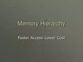
Quick Review: Memory Hierarchy • Memory Hierarchy: Registers, Caches, Main, Disk (upper to lower) • Upper levels faster, costlier • Lower levels larger in capacity • Design Goal: Strive for access time of the highest level for the capacity available at the lowest level • Made possible because of locality of instruction and data references to memory
Memory Hierarchy Processor registers are fastest, but do not use the same address space as the memory Cache memory often consists of 2 (or 3) levels, and technology enables on-chip integration Holds copies of program instructions and data stored in the large external main memory For very large programs, or multiple programs active at the same time, need more storage Use disks to hold what exceeds main memory
Memory Hierarchy with One-Level Cache PROCESSOR CACHE Access Time: 1 unit Capacity: O(10KB) MAIN MEMORY Access Time: 100 units Capacity: O(GB) MAGNETIC DISK Access Time: 107 units Capacity: O(100GB)
Caches and Locality of Reference • The cache is between processor and memory • Makes large, slow main memory appear fast • Effectiveness is based on locality of reference • Typical program behavior involves executing instructions in loops and accessing array data • Temporal locality: instructions/data that have been recently accessed are likely to be again • Spatial locality:nearby instructions or data are likely to be accessed after current access
More Cache Concepts To exploit spatial locality, transfer cache block with multiple adjacent words from memory Later accesses to nearby words are fast, provided that cache still contains the block Mapping function determines where a block from memory is to be located in the cache When cache is full, replacement algorithm determines which block to remove for space
Cache Operation Processor issues Read and Write requestsas if it were accessing main memory directly But control circuitry first checks the cache If desired information is present in the cache, a read or writehit occurs For a read hit, main memory is not involved; the cache provides the desired information For a write hit, there are two approaches
Handling Cache Writes Write-through protocol: update cache & mem. Write-back protocol: only updates the cache; memory updated later when block is replaced Write-back scheme needs modified or dirty bit to mark blocks that are updated in the cache If same location is written repeatedly, then write-back is much better than write-through Single memory update is often more efficient,even if writing back unchanged words
Handling Cache Misses If desired information is not present in cache, a read or writemiss occurs For a read miss, the block with desired word is transferred from main memory to the cache For a write miss under write-through protocol, information is written to the main memory Under write-back protocol, first transfer block containing the addressed word into the cache Then overwrite location in cached block
Mapping Functions • Block of consecutive words in main memory must be transferred to the cache after a miss • The mapping function determines the location • Study three different mapping functions • Use small cache with 128 blocks of 16 words • Block size: 16 words • Cache size: 128x16 = 2048 words • Use main memory with 64K words (4K blocks) • Number of blocks = 64K/16 = 4K • Word-addressable memory, so 16-bit address • 2^16 = 64K
Mapping Functions • Study three different mapping functions • Direct Mapping • Associative Mapping • Set-associative Mapping
Direct Mapping Simplest approach uses a fixed mapping: memory block j cache block ( j mod 128 ) Only one unique location for each mem. block Two blocks may contend for same location New block always overwrites previous block Divide address into 3 fields: word, block, tag Block field determines location in cache Tag field from original address stored in cache Compared with later address for hit or miss
Example Word# 15 0 0 0 1 1 5 bits 16x32 bits . . . Cache Block# V D TAG D A T A 127 One Block Wide Block# Cache Block # = Block # mod 128 Memory Address 0 15 4 3 Word# Block# Cache Address 0 10 4 3 4K-1 Word# Cache Block# One Block Wide
Resulting Partitioning of Memory Address and Address Mapping Memory Address = <Tag, Cache Block #, Word #> where, Tag is 5 bits – range is 0-31 Cache Block # is 7 bits – range is 0-127 Word # is 4 bits – range is 0-15 Example: Memory address <27, 87, 11> will map to Cache Block # 87 and will have a tag value of 27. The addressed word will be Word # 11 in this block.
Associative Mapping Full flexibility: locate block anywhere in cache Block field of address no longer needs any bits Tag field is enlarged to encompass those bits Larger tag stored in cache with each block For hit/miss, compare all tags simultaneously in parallel against tag field of given address This associative searchincreases complexity Flexible mapping also requires appropriate replacement algorithm when cache is full
Set-Associative Mapping Combination of direct & associative mapping Group blocks of cache into sets Block field bits map a block to a unique set But any block within a set may be used Associative search involves only tags in a set Replacement algorithm is only for blocks in set Reducing flexibility also reduces complexity k blocks/set k-way set-associative cache Direct-mapped 1-way; associative all-way
Stale Data Each block has a valid bit, initialized to 0 No hit if valid bit is 0, even if tag match occurs Valid bit set to 1 when a block placed in cache Consider direct memory access, where data is transferred from disk to the memory Cache may contain stale data from memory, so valid bits are cleared to 0 for those blocks Memorydisk transfers: avoid stale data by flushing modified blocks from cache to mem.
LRU Replacement Algorithm The following algorithm implements the FIFO based LRU algorithm by associating and updating the FIFO position of each element in a k–way set dynamically, as new elements are brought in the set or old ones replaced. • For k-way set associativity, each block in a set has a counter ranging from from 0 to k1 • On hit: • Set counter of hit block as 0; increment others with counters lower than original counter value of the hit block • On miss and the set is not full: • Set counter of incoming block as 0 and increment all other block counters by 1 • On miss and the set full: • Replace the block with Counter=k-1, set counter of incoming block as 0 and increment all other block counters by 1
LRU Algorithm in terms of FIFO • FIFO size = number of ways (4 for 4-way set associative) • FIFO positions numbered 0 (for MRU) to 3 (for LRU) • Insertions and promotions at the MRU position • Eviction at the LRU position. • For access to a new block (miss): • Evict block at LRU position (if no room) • Insert the new block at the MRU position (other blocks move one position) • For access to an existing block (hit) • Promote it to the MRU position (other blocks that were ahead in FIFO move one position) Needs log2A bits/block, where A=#ways. Can use smaller FIFO (fewer bits) with reduced accuracy.
LRU Algorithm in terms of FIFO - Example Reference Sequence: 17, 25, 17, 55, 25, 30, 22, 30 29
Cache Performance • Primary Measure: Average Access Time • Can compute for each level of cache in terms of its hit rate (h), cache access time (C) and miss penalty (M): • Then, can combine successive levels, say L1 and L2, by noting that the average miss penalty of L1 is the same as the average access time of L2. Hence, assuming unified L1 cache for instructions and data (not the common case). If $L1D and $L1I are separate, use weighted average.
Example 8.4 • Given: • Cache with two levels: L1 and L2 • Performance data: • L1: access time: T, hit rate: 0.96 • L2: access time: 15T, hit rate: 0.8 • Transfer times: L2 to L1: 15 T, M to L2: 100T • What fraction of accesses miss both L1 and L2? • What is the av. access time seen by processor? • By what factor would it reduce If L2’s hit rate were perfect, i.e. 1.0? • What is the av. access time seen by processor if L2 is removed and L1 is increased so as to halve its miss rate? Note: Answers to (b) – (d) depend on assumptions made about the miss penalty.
Solution • 20% of 4% = .2*.04 = .008 • AMATproc = h1*HTL1 + (1-h1)MPL1 MPL1 = h2*HTL2 + (1-h2)MPL2 MPL2 = HTMain Assume: Whenever the data is transferred from one level of the memory hierarchy to the next lower level, it is also made available to the processor at the same time (assumes additional data paths). Hence: AMATproc = h1*HTL1+ (1-h1)[h2*HTL2 + (1-h2)HTMain] = 0.96*T + 0.04(0.8*15T + 0.2*100T) = 2.24T Parts (c) and (d) can be answered in a similar way.
Performance Enhancement Methods • Use Write Buffer when using write-through. • Obviates the need to wait for the write-through to complete, e.g. the processor can continue as soon as the buffer write is complete. (see further details in the textbook) • Prefetchdata into cache before they are needed. Can be done in software (by user or compiler) by inserting special prefetch instructions. Hardware solutions also possible and can take advantage of dynamic access patterns. • Lockup-Free Cache: Redesigned cache that can serve multiple outstanding misses. Helps with the use of software-implemented prefetching. • Interleaved main memory. Instead of storing successive words in a block in the same memory module, store it in independently accessible modules – a form of parallelism. Latency of first word still the same but the successive words can be transferred much faster.
Virtual Memory (Why?) Physical mem. capacity address space size A large program or many active programs may not be entirely resident in the main memory Use secondary storage (e.g., magnetic disk) to hold portions exceeding memory capacity Needed portions are automatically loaded into the memory, replacing other portions Programmers need not be aware of actions; virtual memory hides capacity limitations
Virtual Memory (What?) Programs written assuming full address space Processor issues virtual or logical address Must be translated into physical address Proceed with normal memory operationwhen addressed contents are in the memory When no current physical address exists, perform actions to place contents in memory System may select any physical address;no unique assignment for a virtual address
Memory Management Unit Implementation of virtual memory relies on a memory management unit (MMU) Maintains virtualphysical address mapping to perform the necessary translation When no current physical address exists, MMU invokes operating system services Causes transfer of desired contents from disk to the main memory using DMA scheme MMU mapping information is also updated
The Big Picture: Full Memory Hierarchy Disk address
Address Translation Use fixed-length unit of pages (2K-16K bytes) Larger size than cache blocks due to slow disks For translation, divide address bits into 2 fields Lower bits give offset of word within page Upper bits give virtual page number (VPN) Translation preserves offset bits, but causes VPN bits to be replaced withpage frame bits Page table (stored in the main memory) provides information to perform translation
Page Table MMU must know location of page table Page table base register has starting address Adding VPN to base register contents gives location of corresponding entry about page If page is in memory, table gives frame bits Otherwise, table may indicate disk location Control bits for each entry include a valid bit and modified bit indicating needed copy-back Also have bits for page read/write permissions
Translation Lookaside Buffer MMU must perform lookup in page tablefor translation of every virtual address For large physical memory, MMU cannot hold entire page table with all of its information Translation lookaside buffer (TLB) in the MMU holds recently-accessed entries of page table Associative searches are performed on the TLB with virtual addresses to find matching entries If miss in TLB, access full table and update TLB
Page Faults A page fault occurs when a virtual address has no corresponding physical address MMU raises an interrupt for operating system to place the containing page in the memory Operating system selects location using LRU, performing copy-backif needed for old page Delay may be long, involving disk accesses, hence another program is selected to execute Suspended program restarts later when ready
Memory Organization: Basic Concepts • Access provided by processor-memory interface • Address and data lines, and also control lines for command (Read/Write), timing, data size • Memory access time is time from initiation to completion of a word or byte transfer • Memory cycle time is minimum time delay between initiation of successive transfers • Random-access memory (RAM) means that access time is same, independent of location
Semiconductor RAM Memories • Memory chips have a common organization • Cells holding single bits arranged in an array • Words are rows; cells connected to word lines (cells per row bits per processor word) • Cells in columns connect to bit lines • Sense/Write circuits are interfaces betweeninternal bit lines and data I/O pins of chip • Common control pin connections includeRead/Write command and chip select (CS)
Memory Chips: Internal Organization • Depends on if address decoding is 1-D or 2-D • Fig. 8.2 shows example of 1-D decoding • Fig. 8.3 shows example of 2-D decoding