Download
1 / 21
210 likes | 435 Views
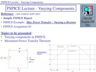
PSPICE Lecture - Varying Components. 1. PSPICE Lecture - Varying Components. Reference : (see course web site) Sample PSPICE Report PSPICE Example: Max Power Transfer - Varying a Resistor PSPICE Assignment #3. Topics to be presented : Varying components in PSPICE

E N D
PSPICE Lecture - Varying Components 1 PSPICE Lecture - Varying Components • Reference: (see course web site) • Sample PSPICE Report • PSPICE Example: Max Power Transfer - Varying a Resistor • PSPICE Assignment #3 • Topics to be presented: • Varying components in PSPICE • Maximum Power Transfer Theorem
PSPICE Lecture - Varying Components 2 DC Sweep • A DC Sweep analysis in PSPICE can be used to vary a: • Voltage source • Current Source • Global parameter (such as a resistor, inductor, or capacitor) • Model parameter (such as a constant in a PSPICE model) • Temperature Covered in PSPICE Lecture #2 Covered here in PSPICE Lecture - Varying Components Quantities that can be varied using a DC Sweep
PSPICE Lecture - Varying Components 3 Varying a component (Global Parameter) in PSPICE Follow these steps to vary a component in PSPICE: Draw the schematic using a variable part for the component to be varied. For example, use part R_var, not R. Similarly, use part C_var to vary a capacitor. Change the value of the part to a name in braces. For example, change 1k to {Rvalue}. Change SET. Double-click on the part and change the property named SET from 0.5 to 1. Also display this property. The value of R is actually multiplied by SET, so using SET = 0.5 is confusing.
PSPICE Lecture - Varying Components 4 Varying a component (Global Parameter) in PSPICE (continued) • Add a part named PARAM. Place the part (it will appear as PARAMETERS) on the schematic next to the circuit. PARAM is located in the SPECIAL library. • Add a property (column) to PARAM. • Double-click on PARAMETERS to open the Property Editor. • Select New Column to add a new property to PARAM. • Name the New Column Rvalue (the name usesd for the variable resistor. • Give the New Column a Value of 1 (any value).
PSPICE Lecture - Varying Components 5 Varying a component (Global Parameter) in PSPICE (continued) • Display the new property. The new property just added will not be shown by default. In general, always display and new values added or any values that are altered in PSPICE. To display the property: • Double-click on PARAMETERS to open the Property Editor. • Scroll through the properties to find and select the new property added (Rvalue). • Select Display to open the Display Properties window. Select Name and Value. • Close the Display Properties window and note the change to the schematic.
PSPICE Lecture - Varying Components 6 Varying a component (Global Parameter) in PSPICE (continued) • Create a Simulation Profile. • Select PSPICE – New Simulation Profile • Change the Analysis type to DC Sweep • Select Global parameter • Select Logarithmic for this example and vary Rvalue from 500 to 50k. • Using 50 points/Decade will result in a total of 100 points in this example. • Select OK. Note that nodes A and B were labeled on the schematic. This will make it easier to refer to the output voltage, V(B), later.
PSPICE Lecture - Varying Components 7 Varying a component (Global Parameter) in PSPICE (continued) Analyze the circuit. Select PSPICE – Run Graph Power vs Resistance for R1 Select Add Traces and enter the expression for the power to resistor R1: V(B)*V(B)/Rvalue
PSPICE Lecture - Varying Components 8 Varying a component (Global Parameter) in PSPICE (continued) Graph Power vs Resistance for R1 Select Add Traces (or use toolbar) and enter the expression for the power to resistor R1: V(B)*V(B)/Rvalue Select Plot – X-axis and change the range to 500 to 50k Select Plot – Y axis and change the range to 0 to 500m.
PSPICE Lecture - Varying Components 9 Varying a component (Global Parameter) in PSPICE (continued) Graph Power vs Resistance for R1 Select Trace – Cursor – Display (or use toolbar) to turn on the cursor Select Trace – Cursor – Peak (or use toolbar) to move the cursor to the peak Select Plot – Label – Mark (or use toolbar) to mark the point Select Plot – Label – Text (or use toolbar) to add text to the graph
PSPICE Lecture - Varying Components 10 Varying a component (Global Parameter) in PSPICE (continued) Graph Power vs Resistance for R1 Select Window – Copy to Clipboard to copy the graph (with a white background) to the clipboard where you can paste it into Word or elsewhere.
PSPICE Lecture - Varying Components 11 Operational Amplifiers Operational amplifiers can be analyzed in PSPICE using different models, including: Using specific part from the EVAL library, such as the uA741 Use a general op amp circuit model consisting of a dependent source and a resistor Typical values for the op amp model shown: AOL = 100,000 R = 2M - 10M
PSPICE Lecture - Varying Components 12 Example Analyze the following op amp circuit (find Vo and Io): By hand Using PSPICE with the uA741 op amp Using PSPICE with a general op amp model (dependent source and resistor) 30k _ 10k Vo Io + - + 6V 9k Hand Analysis:
PSPICE Lecture - Varying Components 13 PSPICE analysis with the uA741 op amp: Draw the schematic. Use the uA741 from the EVAL library. Ignore the connections labeled OS1 and OS2. In practical lab situations, an adjustable resistor (potentiometer) can be connected between these terminals to “zero” the op amp (to set the output to 0V when the input is 0V). This is somewhat like zeroing your bathroom scale.
PSPICE Lecture - Varying Components 14 Add voltage sources to power the op amp. The value of the voltage sources depends on Vo. In general, the source voltages should be greater than Vo. In practical situations, it is recommended that they be greater by at least 2V. Since Vo = -18V, supply voltages of +20V and -20V have been added below.
PSPICE Lecture - Varying Components 15 Note: To avoid crowding, the supply voltages can be placed to the side and connected to the circuit using OFFPAGE Connectors. Note the name of the OFFPAGE connector also serves as a node label.
PSPICE Lecture - Varying Components 16 • Add voltage and current printers to measure Io and Vo. • Be sure to change the DC property on each printer to Yes and display the property. • Be sure to place the current printer in series and place the voltage printer in parallel. • It is also a good idea to label the node for the output voltage as Vo.
PSPICE Lecture - Varying Components 17 Create a New Simulation Profile, Run PSPICE, and view the results in the OUTPUT file. A portion of the .OUT file Note that the results match the hand analysis: Vo = -18V and Io = -2.6 mA
PSPICE Lecture - Varying Components 18 PSPICE analysis using a model consisting of a dependent source and a resistor: Draw the schematic. Use Rin = 2M and AOL = 100,000 Substitute op amp model In place of op amp in circuit 30k _ 10k Vo Io + - + 6V 9k
19 PSPICE Lecture - Varying Components Dotted lines not part of schematic. Added for emphasis. Draw the schematic (continued). Use Rin = 2M and AOL = 100,000 (exact values are not critical)
PSPICE Lecture - Varying Components 20 • Add voltage and current printers to measure Io and Vo. • Be sure to change the DC property on each printer to Yes and display the property. • Be sure to place the current printer in series and place the voltage printer in parallel. • It is also a good idea to label the node for the output voltage as Vo.
PSPICE Lecture - Varying Components 21 Create a New Simulation Profile, Run PSPICE, and view the results in the OUTPUT file. Note that the results match the hand analysis: Vo = -18V and Io = -2.6 mA