Download
1 / 5
50 likes | 171 Views
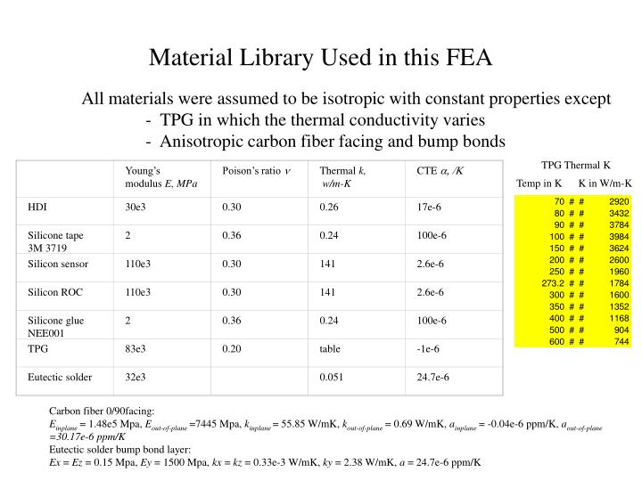
Young’s modulus E, MPa. Poison’s ratio n. Thermal k, w/m-K. CTE a, /K. HDI. 30e3. 0.30. 0.26. 17e-6. Silicone tape 3M 3719. 2. 0.36. 0.24. 100e-6. Silicon sensor. 110e3. 0.30. 141. 2.6e-6. Silicon ROC. 110e3. 0.30. 141. 2.6e-6. Silicone glue NEE001. 2. 0.36. 0.24.

E N D
Young’s modulus E, MPa Poison’s ratio n Thermal k, w/m-K CTE a, /K HDI 30e3 0.30 0.26 17e-6 Silicone tape 3M 3719 2 0.36 0.24 100e-6 Silicon sensor 110e3 0.30 141 2.6e-6 Silicon ROC 110e3 0.30 141 2.6e-6 Silicone glue NEE001 2 0.36 0.24 100e-6 TPG 83e3 0.20 table -1e-6 Eutectic solder 32e3 0.051 24.7e-6 Material Library Used in this FEA All materials were assumed to be isotropic with constant properties except - TPG in which the thermal conductivity varies - Anisotropic carbon fiber facing and bump bonds TPG Thermal K Temp in K K in W/m-K Carbon fiber 0/90facing: Einplane = 1.48e5 Mpa, Eout-of-plane =7445 Mpa, kinplane= 55.85 W/mK, kout-of-plane = 0.69 W/mK, ainplane = -0.04e-6 ppm/K, aout-of-plane=30.17e-6 ppm/K Eutectic solder bump bond layer: Ex = Ez = 0.15 Mpa, Ey = 1500 Mpa, kx = kz = 0.33e-3 W/mK, ky = 2.38 W/mK, a = 24.7e-6 ppm/K
RESULTS WITH CF/TPG/CF SUBSTRATE 0.6 mm (0.12+0.38+0.12) mm COOLING AT ENDS Overall ∆T = 22C From +7C to +29C Heat Load = 2.28W , Half Model with 4 chips ∆T, substrate = 12.8C From +7C to 19.8C ∆T, HDI = 14.6C From +12.2C to +26.8C ∆T, sensor/ROC = 2.9C From +26.1C to +29C
RESULTS WITH CF/TPG/CF SUBSTRATE 0.6 mm (0.12+0.38+0.12) mm COOLING AT ENDS Heat Load = 2.28W , Half Model with 4 chips Max resultant displacement = 2 microns
RESULTS WITH CF/TPG/CF SUBSTRATE 0.6 mm (0.12+0.38+0.12) mm COOLING AT ENDS Heat Load = 2.28W , Half Model with 4 chips TPG Layer Max Resultant Stress = 1.25 Mpa Max Stress_Z = 0.13 Mpa Flexural Strenth = 36.7 Mpa Z = 38.5 Mpa // Tensile Strength < 0.69 Mpa Z = 6,897 Mpa // Stress Z Plot (out-of-plane direction)
RESULTS WITH CF/TPG/CF SUBSTRATE 0.6 mm (0.12+0.38+0.12) mm COOLING AT ENDS Heat Load = 2.28W , Half Model with 4 chips Stress Resultant Plot Stress Z Plot (out-of-plane 900direction) Carbon Fiber Layer Max Resultant Stress_X = 0.1 Mpa Max Stress_Z = 0.9 Mpa Flexural Strenth = 669 Mpa 00 Tensile Strength =1950 Mpa 00 = 28 Mpa 900