Download
1 / 22
220 likes | 303 Views
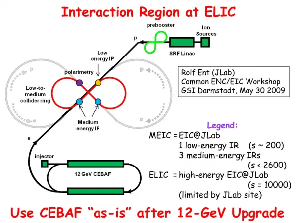
The Interaction Region. M. Sullivan 5 th SuperB Workshop Paris May 9-11, 2007. Outline. Design Issues IR Design Toward an improved design Summary. Detector Considerations. Reasonable angular acceptance ± 300 mrad Small radius beam pipe 10 mm radius Thin beam pipe SR backgrounds

E N D
The Interaction Region M. Sullivan 5th SuperB Workshop Paris May 9-11, 2007
Outline • Design Issues • IR Design • Toward an improved design • Summary
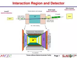
Detector Considerations • Reasonable angular acceptance • ±300 mrad • Small radius beam pipe • 10 mm radius • Thin beam pipe • SR backgrounds • Rates comparable to PEP-II • Few hits per crossing on Be beam pipe • Little or no hits on nearby beam pipes
Detector Considerations (2) • BGB backgrounds • Keep nearby upstream bending to a minimum • Suggest upstream bending further away from the detector (>10 m) to minimize the BGB integral • Low vacuum pressure upstream of the detector
Detector Considerations (3) • Luminosity backgrounds • Beam lifetimes • Radiative bhabhas • Beam-beam • Local HOM power • Small diameter beam pipes trap higher frequencies • Always get modes when two pipes merge to one
Accelerator parameters LER HER Energy (GeV) 4.0 7.0 Current (A) 3.95 2.17 No. bunches 3466 Bunch spacing (m) 0.63 Beat x* (mm) 20 20 Beta y* (mm) 0.2 0.2 Emittance x (nm-rad) 1.6 1.6 Emittance y (pm-rad) 4 4 Full crossing angle (mrad) 34 These parameters constrain or define the IR design
Summary of Present Design • Crossing angle of ±17 mrad • Beam pipe diameter of 20 mm at the end of QD0 for both beams (same size as IP pipe) • This leaves enough room (~10 mm) to place a permanent magnet quadrupole and get the required strength (Using Br = 14 kG) • We have placed small bending magnets between QD0 and QF1 on the incoming beam lines to redirect the QF1 SR • The septum QF1 magnets for the outgoing beams are tilted in order to let the strong SR fans escape • The outgoing beams B0 magnets are a C shape design in order to allow the strong SR fans to escape
IR design parameters Length Starts at Strength Comments L* 0.30 m 0.0 Drift QD0 0.46 m 0.30 m -820.6 kG/m Both HER and LER QD0H 0.29 m 0.76 m -820.6 kG/m HER only B00L 0.40 m -1.05 m -2.2 kG Incoming LER only B00H 0.40 m 1.05 m 1.5 kG Incoming HER only QF1L 0.40 m ±1.45 m 293.2 kG/m LER only QF1H 0.40 m ±1.45 m 589.1 kG/m HER only B0L 2.0 m ±2.05 m 0.3 kG LER only (sign?) B0H 2.0 m ±2.05 m 0.526 kG HER only (sign?) QD0 offset 6.00 mm Incoming HER QD0 offset 7.50 mm Incoming LER
SR Power Numbers The design (G3) has a total SR power comparable to PEP-II SR power in QD0 (kW) for beam currents of 1.44A HER and 2.5A LER No QD0 offsets Ver. F1 Ver. G3 PEP-II 3A on 1.8A Incoming HER 41 9 4 49 Incoming LER 28 1 1 16 Outgoing HER 41 152 93 49 Outgoing LER 28 67 55 16 Total 138 230 153 130
Some SR background details • We are using a gaussian beam distribution with a second wider and lower gaussian simulating the “beam tails” • The beam distribution parameters are the same as the ones used for PEP-II • We allow particles out to 10 in x and 35 in y to generate SR • Unlike in PEP-II the SR backgrounds in the SuperB are dominated by the particle distribution at large beam sigma, so we are more sensitive to the exact particle distribution out there
Radiative Bhabhas • The outgoing beams are still significantly bent as they go through QD0 • Therefore the off-energy beam particles from radiative bhabhas will get swept out • Knowing this, we will have to build in shielding for the detector
How to improve the design • The best improvement would be to reduce the radiative bhabha background • Note that there is only a small gain in beam separation from the strong outgoing bending because one has to allow the outgoing SR to escape (see slide 14) • The only gain comes from the BSC moving away from the septum
Attempts to improve the design • Three possibilities so far looked at • Reduce the strength of the shared element • Difficult to control beta functions (Can’t let the beta functions get too big) • Try a high strength but very short and close to the IP shared element (minimal off-axis trajectories) • Need a VERY high strength field to control beta functions • High field still bends a beam even with a small off-axis traj. • Eliminate the shared element • Wants a maximum crossing angle (±24 mrads?) • Can start one focusing magnet for one of the beams first and then follow with the focusing magnet for the other beam as soon as possible • Still need to control beta functions • Just got started on this option: no conclusion yet
More designs • Other possibilities thought about • A longer, weaker shared element • End up with more bending at the outboard end • Wants a minimal crossing angle • Difficult to control beta functions • Asymmetric IR (more like ILC?) • Well controlled incoming beta functions • Outgoing beta functions allowed to get bigger • OK for ILC—not so good for storage rings
Summary • We have an IR design that has acceptable SR backgrounds with a crossing angle of ±17 mrad and an energy asymmetry of 7x4 • The BGB and coulomb scattered beam particles as a background need to be calculated and controlled (been done?) • Radiative bhabha backgrounds are still high due to the strong bending of the outgoing beams • The total SR power generated by the IR is high for the same reason. This can cause emittance growth. Especially vertical emittance growth since this is in a coupled region. • A through exploration of parameter space is needed to find the best IR design