Download
1 / 25
250 likes | 321 Views
Accelerator and Interaction Region. Alex Bogacz Center for Advanced Studies of Accelerators. EIC Detector Workshop at Jefferson Lab June 4-5, 2010. EIC Efforts at JLab. For over a year…

E N D
Accelerator and Interaction Region Alex Bogacz Center for Advanced Studies of Accelerators EIC Detector Workshop at Jefferson Lab June 4-5, 2010
EIC Efforts at JLab For over a year… • We have explored a staged approach to EIC, focusing on science cases and accelerator designs for a low-to-medium energy EIC with similar design features (high luminosity (>1034), polarization (>80%), multiple detectors) • We have developed a conceptual design of a low-to-medium energy EIC based on CEBAF, and have therefore reduced the detector and accelerator technology R&D significantly, yielding a large cost saving compared to the full energy collider. • We are now engaged in accelerator design, optimizations and staged R&D for enabling technologies.
Design Goals • Energy • Electrons: 3 to 11 GeV • Ions: 20-60+ GeV protons, ~30 GeV/A ions • Luminosity • a few1034 cm-2 s-1 per interaction point over a wide range of s values • Multiple interaction points • Ion Species • Polarized H, D, 3He, possibly Li • Up to A = 208, all fully stripped • Polarization • Longitudinal at the IP for both beams, transverse for ions • Spin-flip for the electron beam: • All polarizations >80% desirable • Positron Beam desirable
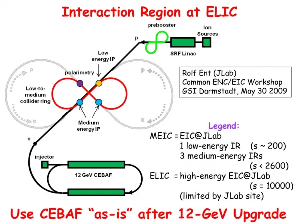
Design Features • High luminosity at medium energy range • Enabled by short ion bunches, low β*, high rep. rate • Require crab crossing colliding beams • Electron cooling is an essential part of MEIC • Multiple IPs (detectors) • “Figure-8” electron and ion collider rings • Ensure spin preservation & ease spin manipulations • No spin sensitivity to energy for all species. • 12 GeV CEBAF injector meets storage-ring polarized beam requirements, can serve as a full energy injector
Conceptual Layout • Three compact rings: • 3 to 11 GeV electron • Up to 12 GeV/c proton (warm) • Up to 60 GeV/c proton (cold)
Collider Rings with ‘Relaxed’ IR Optics • Larger Figure-8 Rings (~1000 m circumference) • 5 Tesla bends for ions at 60 GeV • Additional straights to accommodate spin rotators and RF • Horizontal IR crossing, dispersion free straights • ‘Relaxed’ IR Design: • Chromaticity Compensating Optics • Uncompensated dispersion in the straights • Anti-symmetric dispersion pattern across the IR • Dedicated Symmetric Inserts around the IR • Electron Collider Ring based on emittance preserving Optics
Figure-8 Collider Ring • Collider Ring design is a compromise between: • Minimizing synchrotron radiation effects prefers a large size ring • Space charge effect of ion beam prefers a compact ring total ring circumference: 1000 m 64 deg. crossing
Ion Ring – 900 FODO Cell phase adv/cell: Dfx,y= 900 Arc quadrupoles: $Lb=40 cm $G= 14.4 kGauss/cm Arc dipoles: $Lb=180 cm $B=60.0 kGauss $ang=3.09 deg. $rho = 33.4 meter Arc quadrupoles $Lb=40 cm $G= 10.1kG/cm beta chromaticity perturbation wave propagates with twice the betatron frequency – intrinsic cell-to-cell cancellation of chromatic terms (after two cells)
Ion Ring - Arc Optics 248 deg. Arc Arc – 120 meter Arc – 120 meter Straight – 20 meter
Electron Ring – 1350 FODO Cell Synchrotron radiation power per meter less than 20 kW/m phase adv/cell: Dfx,y= 1350 Arc dipoles, 9 GeV: $Lb=100 cm $B=16.2 kGauss $ang=3.09 deg. $rho = 18.4 meter emittance preserving optics Quadrupoles $Lq=50 cm $G= ±4.5 kG/cm <H> minimum 1350 FODO
Electron Ring - Arc Optics 248 deg. Arc Arc – 120 meter Arc – 120 meter Straight – 20 meter
IR Optics (electrons) 5 800 BETA_X&Y[m] DISP_X&Y[m] 0 0 0 BETA_X BETA_Y DISP_X DISP_Y 19 Natural Chromaticity: x = -47 y = -66 IP f l * = 3.5m FF doublets
5 800 0.15 0.15 BETA_X&Y[m] DISP_X&Y[m] Size_X[cm] Size_Y[cm] 0 0 0 0 0 BETA_X BETA_Y DISP_X DISP_Y 19 0 Ax_bet Ay_bet Ax_disp Ay_disp 19 IR Optics (electrons at 5 GeV) IP IP Q1 G[kG/cm] = -2.8 Q2 G[kG/cm] = 3.1 Q3 G[kG/cm] = -2.0 Q4 G[kG/cm] = 2.0 Q4 Q3 Q2 Q1
IR Optics (ions) 5 3000 BETA_X&Y[m] DISP_X&Y[m] 0 0 0 BETA_X BETA_Y DISP_X DISP_Y 50 Natural Chromaticity: x = -88 y = -141 IP f l * = 7m FF triplet : Q3 Q2 Q1
5 3000 0.25 0.25 BETA_X&Y[m] DISP_X&Y[m] Size_X[cm] Size_Y[cm] 0 0 0 0 0 BETA_X BETA_Y DISP_X DISP_Y 50 0 Ax_bet Ay_bet Ax_disp Ay_disp 50 IR Optics (ions) at 60 GeV IP IP FF triplet : Q3 Q2 Q1 Q1 G[kG/cm] = -9.7 Q2 G[kG/cm] = 6.9 Q3 G[kG/cm] = -6.8
Chromaticity Compensation uncompensated dispersion from the Arc Dfx = 2 Dfy Dfx = p • Pairs of sextupoles ‘minus identity’ apart – cancelation of spherical aberrations • Cancelation of higher order chromatic terms due to symmetry imposed correlations
IR Chromaticity Compensation ions IP Arc end Dfx,y = p Dfx = p Dfx = p Dfy = 3p Chromaticity Compensation with four families of sextupoles
Chromaticity Compensation electrons IP Arc end Dfx = p Dfx = p Dfx,y = p Chromaticity Compensation with four families of sextupoles
32 31 36 37 1 2 3 4 5 Collider Ring – Tune Diagram Working point above half integer a la KEKB: Qx=36.506 Qy=31.531
Tune Chromaticity Correction Large momentum acceptance and dynamic aperture
Figure-8 Collider Rings total ring circumference: 1000 m
Figure-8 Collider Rings total ring circumference: 1000 m
Summary • MEIC EIC at JLab promises to accelerate and store a wide variety of polarized light ions and un-polarized heavy ions in collision with polarized electron or positron beam enabling a unique physics program. • The project covers a wide CM energy range (10 to 100 GeV) in a coherent way. In the immediate future, a low-to-medium energy collider (CM energy 10 to 50 GeV) is our immediate goal & R&D focus. • The collider luminosity for e-p collisions should reach ~1034 cm-2s-1 at (60x3~52 GeV2) • The project is now based on mostly proven accelerator technologies. Making a high intensity ion beam with high repetition rate, small emittance and short bunch length is a key to reaching the luminosity goals (advanced cooling techniques are required). • We have identified critical accelerator R&D topics for the project, We are currently pursuing staged accelerator design studies to validate and further optimize our design.