Download
1 / 40

E N D
Chapter 18 ISOMETRIC PROJECTION Isometric projection is a type of an axonometric projection (or pictorial projection). Isometric means ‘equal measure’. As the name suggests, in isometric projection, all the mutually perpendicular plane surfaces of an object and the edges formed by these surfaces are equally inclined to a POP. In isometric projection, only one view on a plane is drawn to represent the three dimensions of an object. This provides a pictorial view with a real appearance.
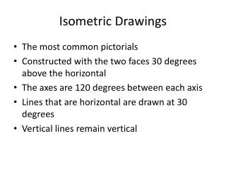
PRINCIPLE OF ISOMETRIC PROJECTION Consider a cube ABCDEFGH resting on one of its corners, say A, at origin ‘O’ and the body diagonal through that corner, i.e., AG, equally inclined to the three axes—X, Y and Z, as shown in Fig. 18.1. The three edges of the cube through the corner A will lie along the three axes. The three faces of the cube formed by these edges will be coincident with the three RPs— the HP, the VP and the PP. Now, consider another plane UVW inclined equally to the three RPs and perpendicular to the body diagonal, AG. This plane makes approximately 54°44’ to each RP. The projection of cube ABCDEFGH obtained on the plane UVW is called an isometric projection. As AG is perpendicular to the plane UVW, it is seen as a point view in isometric projection. The three mutually perpendicular edges AB, AD and AE make equal angles, i.e., 120° to each other in isometric projection. The edges CB and CD make angles of 30° each with a horizontal line passing through C. The edges AE, BF, CG and DH are seen vertical. The edges CB and CD make angles of 60° each with CA. It should be noted that, as all the edges of a cube are equally inclined to the POP, they get equally foreshortened in isometric projection. Thus, the isometric projection is smaller than the real object.
TERMINOLOGY Isometric axes The three lines GH, GF and GC meeting at point G and making 120° angles with each other are termed isometric axes, Fig. 18.3(a). Isometric axes are often shown as in Fig. 18.3(b). The lines CB, CG and CD originate from point C and lie along X-, Y- and Z-axis respectively. The lines CB and CD make equal inclinations of 30° with the horizontal reference line. The line CG is vertical. In isometric, we show length (or width) of the object along the X-axis, height on the Y-axis and width (or length) on the Z-axis. It may be noted that the choice of axes is arbitrary and it depends on the direction of viewing the object.
Isometric linesThe lines parallel to the isometric axes are called isometric lines or isolines. A line parallel to the X-axis may be called an x-isoline. So are the cases of y-isoline and z-isoline. Non-Isometric linesThe lines which are not parallel to isometric axes are called non-isometric lines or non-isolines. The face-diagonals and body diagonals of the cube shown in Fig. 18.1 are the examples of non-isolines. Isometric planesThe planes representing the faces of the cube as well as other faces parallel to these faces are called isometric planes or isoplanes. Note that isometric planes are always parallel to any of the planes formed by two isometric axes. Non-Isometric planesThe planes which are not parallel to isometric planes are called nonisometric planes or non-isoplanes (or non-isometric faces). Origin or Pole PointThe point on which a given object is supposed to be resting on the HP or ground such that the three isometric axes originating from that point make equal angles to POP is called an origin or pole point.
ISOMETRIC SCALE As explained earlier, the isometric projection appears smaller that the real object. This is because all the isometric lines get equally foreshortened. The proportion by which isometric lines get foreshortened in an isometric projection is called isometric scale. It is the ratio of the isometric length to the actual length. The isometric scale, shown in Fig. 18.4, is constructed as follows: 1. Draw a base line OA. 2. Draw two lines OB and OC, making angles of 30° and 45° respectively with the line OA. 3. The line OC represents the true scale (i.e., true lengths) and line OB represents isometric scale (i.e., isometric lengths). Mark the divisions 1, 2, 3, etc., to show true distances, i.e., 1cm, 2cm, 3cm, etc., on line OC. Subdivisions may be marked to show distances in mm. 4. Through the divisions on the true scale, draw lines perpendicular to OA cutting the line OB at points 1, 2, 3, etc. The divisions thus obtained on OB represent the orresponding isometric distances.
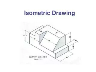
ISOMETRIC PROJECTIONS AND ISOMETRIC VIEWS Isometric projection is often constructed using isometric scale which gives dimensions smaller than the true dimensions. However, to obtain isometric lengths from the isometric scale is always a cumbersome task. Therefore, the standard practice is to keep all dimensions as it is. The view thus obtained is called isometric view or isometric drawing. As the isometric view utilises actual dimensions, the isometric view of the object is seen larger than its isometric projection. Fig. 18.5 shows the isometric projection and isometric view of a cube.
ISOMETRIC VIEWS OF STANDARD SHAPES Square Consider a square ABCD with a 30 mm side as shown in Fig. 18.6. If the square lies in the vertical plane, it will appear as a rhombus with a 30 mm side in isometric view as shown in either Fig. 18.6(a) or (b), depending on its orientation, i.e., right-hand vertical face or left-hand vertical face. If the square lies in the horizontal plane (like the top face of a cube), it will appear as in Fig.18.6(c). The sides AB and AD, both, are inclined to the horizontal reference line at 30°.
Rectangle A rectangle appears as a parallelogram in isometric view. Three versions are possible depending on the orientation of the rectangle, i.e., right-hand vertical face, left-hand vertical face or horizontal face, as shown in Fig. 18.7.
Triangle A triangle of any type can be easily obtained in isometric view as explained below. First enclose the triangle in rectangle ABCD. Obtain parallelogram ABCD for the rectangle as shown in Fig. 18.8(a) or (b) or (c). Then locate point 1 in the parallelogram such that C–1 in the parallelogram is equal to C–1 in the rectangle. A–B–1 represents the isometric view of the triangle.
Pentagon Enclose the given pentagon in a rectangle and obtain the parallelogram as in Fig. 18.9(a) or (b) or (c). Locate points 1, 2, 3, 4 and 5 on the rectangle and mark them on the parallelogram. The distances A–1, B–2, C–3, C–4 and D–5 in isometric drawing are same as the corresponding distances on the pentagon enclosed in the rectangle.
Hexagon The procedure for isometric drawing of a hexagon is the same as that for a pentagon. In Fig. 18.10, the lines 2–3, 3–4, 5–6 and 6–1 are non-isolines. Therefore, the points 1, 2, 3, 4, 5, 7 and 6 should be located properly as shown.
Circle The isometric view or isometric projection of a circle is an ellipse. It is obtained by using four-centre method explained below. Four-Centre MethodIt is explained in Fig. 18.11. First, enclose the given circle into a square ABCD. Draw rhombus ABCD as an isometric view of the square as shown. Join the farthest corners of the rhombus, i.e., A and C in Fig. 18.11(a) and (c). Obtain midpoints 3 and 4 of sides CD and AD respectively. Locate points 1 and 2 at the intersection of AC with B–3 and B–4 respectively. Now with 1 as a centre and radius 1–3, draw a small arc 3–5. Draw another arc 4–6 with same radius but 2 as a centre. With B as a centre and radius B–3, draw an arc 3–4. Draw another arc 5–6 with same radius but with D as a centre. Similar construction may be observed in relation to Fig. 18.11(b).
Any irregular Shape Any irregular shape 1–2–3–4–5–6–7 can be drawn in isometric view as explained in Fig. 18.16. The figure is enclosed in a rectangle first. The parallelogram is obtained in isometric for the rectangle as shown. The isolines B–2, D–2, C–3, E–3, G–4, F–4, H–5, H–6 and A–7 has the same length as in original shape, e.g., B–2 in isometric = B–2 in irregular shape.
ISOMETRIC VIEWS OF STANDARD SOLIDS Prisms The isometric view of a hexagonal prism is explained in Fig. 18.17. To obtain the isometric view from FV and SV, the FV is enclosed in rectangle abcd. This rectangle is drawn as a parallelogram ABCD in isometric view. The hexagon 1–2–3–4–5–6 is obtained to represent the front face of the prism in isometric as explained in Section 18.6.5. The same hexagon is redrawn as 1’–2’–3’–4’–5’–6’ to represent the back face of the prism in such a way that 1–1’ = 2–2’ = 3–3’ = … = 6–6’ = 50 mm. The two faces are then joined together as shown. The lines 1–1’, 2–2’, 3–3’, 4–4’, 5–5’ and 6–6’ are isolines. The lines 5’–6’, 6’–1’ and 1’–2’ are invisible and need not be shown.
Pyramids Figure 18.18 explains the isometric view of a pentagonal pyramid. The base is enclosed in a rectangle abcd, which is drawn as parallelogram ABCD in isometric. The points 1, 2, 3, 4 and 5 are marked in parallelogram as explained in Section 18.6.4. Mark point O1 in isometric such that 4–O1 in isometric is equal to 4–o1 in TV. Draw vertical O1–O = o1’–o’ to represent the axis in isometric projection. Finally join O with 1, 3, 4 and 5 to represent the slant edges of the pyramid.
Cone The isometric view of the cone can be obtained easily from its FV and TV, as shown in Fig. 18.19. The circle (i.e., base of cone) is seen as an ellipse in isometric and is drawn here by using the four-centre method. The point O1 is the centre of the ellipse. Through O1, draw O–O1 = Length of axis. Then, join O to the ellipse by two tangent lines which represent the slant edges of the cone.
Cylinder The isometric view of a cylinder is shown in Fig. 18.20. The base is obtained as an ellipse with centre O. The same ellipse is redrawn (with O1 as a centre) for the top face at a distance equal to the height of the cylinder. The two ellipses are joined by two tangent lines, A–A1 and B–B1, which represent the two extreme generators of the cylinder.
Sphere Figure 18.21 shows the orthographic view and isometric projection of the sphere. The sphere of centre O and radius = 25 is resting centrally on the square slab of size 50 x 50 x 15 with point P as a point of contact. To obtain the isometric projection, an isometric scale is used and the slab of size iso50 x iso50 x iso15 is obtained. The point P, which represents the point of contact between the slab and the sphere, is located at the centre of the top parallelogram. The length of PO in isometric projection is equal to iso25, which is obtained from the isometric scale. Obviously, this length will be shorter than the length of PO in orthographic. Now, with O as a centre and radius equal to 25, a circle is drawn which represents the sphere in isometric.
The isometric view of the sphere is shown in Fig. 18.22. Spherical scale, shown in Fig. 18.23, is used to obtain the radius of the sphere in isometric view.
To draw the isometric view of the sphere in contact with the slab, first draw the isometric view of the slab. Mark point of contact P at the centre of the top face of the slab. Now, through P draw vertical line PO = true radius of the sphere. Obtain the radius of the sphere in isometric view from the spherical scale, i.e., sph25. With O as a centre and radius = sph25, draw a circle to represent the sphere in isometric view.
ISOMETRIC VIEWS OF THE SOLIDS HAVING NON-ISOMETRIC FACES Any face inclined to the isometric plane is called a non-isometric face. Therefore, isometric projections or views of non-isometric faces are obtained by drawing their edges in isometric. Clearly, one must locate the end points of non-isolines forming a non-isometric face. Example 18.1 Figure 18.24(a) shows the FV and LHSV of a truncated triangular prism. Draw its isometric view about the origin O. Solution Enclose given FV and RHSV in rectangles abco and ocdg. Mark point 1’ both in FV and LHSV as shown. The face represented by o–1’ in LHSV is a non-isometric face. This face is seen as a triangle a–1’– o in FV. Figure 18.24(b) shows the required isometric view. 1. Draw an isometric box OABCDEFG having OA = oa, OC = oc and OG = og. Mark point 1 on CB such that C–1 = c–1’. Join O–1– A. It shows a fictitious triangular face of the prism. In the figure it is drawn for the sake of understanding only. Note that O–1– A is an isometric face. In fact, the point 1 will not be seen on CB.
2. Draw x-isoline 1–1” equal to cd. Mark 1’ on 1–1” such that 1–1’ = c–1’. Join O–1’– A. The nonisometric triangular face O–1’–A represents the real face of the truncated prism. Note that we have located the end points of the non-isometric lines O–1’ and A–1’ to obtain this face. 3. Join O– G–1”–1’. The edges GF, F–1” and AF will not be visible and hence need not be drawn.
Example 18.2 Figure 18.25(a) shows the FV and TV of a cut pentagonal prism. Draw its isometric view. Solution Enclose the TV in a rectangle pqrs. As shown in Fig. 18.25(b), obtain parallelogram PQRS in isometric and then mark points ABCDE to represent the base of the prism. Note that PA = pa, QB = qb, QC = qc, PE = pe and SD = sd. Lines AE, ED, DC and CB are non-isolines. Now, through each corner of base draw vertical lines and mark points F, G, 3, 4 and 5 on them such that AF = BG = a’f’, C–3 = E–5 = c’–3’ and D–4 = d’–4’. To mark points 1 and 2 in isometric, draw parallelogram TUMN to represent the rectangle pqmn. Mark points 1 and 2 on MN such that N–1 = M–2 = n–1 = m–2. Join points 1–2–3–4–5 to represent the cut face of the prism. Note that, the points 1, 2, 3, 4 and 5 are located by measuring their distances along the isometric axes.
Example 18.4 Figure 18.28(a) shows the FV and TV of a truncated cylinder. Draw its isometric view. Solution Refer Fig. 18.28(b). To draw an isometric view of the base, the TV is enclosed in a square as usual. The rhombus is obtained for the square in isometric. The circle is obtained as an ellipse by the method of points as explained in Section 18.6.6, Fig. 18.12. The ellipse for the top face can be obtained in a similar way. Join the two ellipses by two tangent lines. In rhombus JKLM, locate point 1’ and 2’ such that J–1’ = M–2’ = e’–1’. Join 1’–2’ par and mark its intersections with top ellipse as 1 and 2. 1–2 represents the edge formed at the top face of the cylinder. To draw a non-isometric elliptical face, adopt the following procedure: 1. Join AE. Locate points F, G, H and I on it in such a way that EF = e’f’, EG = e’g’, EH = e’h’ and EI = e’i’. 2. Draw x-isolines F– F1, G– G1, H– H1, I– I1 such that F– F1 = f’–3’, G–G’ = g’–4’, H– H1 = h’–5’ and I– I1 = I’–6’. Now, through F1, G1, H1 and I1, draw z-isolines 3–11, 4–10, 5–9 and 6–8 respectively taking their lengths from TV. 3. Join 2–3–4–5–6–7–8–9–10–11–1 by a smooth freehand curve. It represents the required nonisometric face.
Note that the line ST, which is tangent to the bottom and top ellipses will be seen from S to N only. The point N represents the point of tangency with the non-isometric curve.
ISOMETRIC VIEWS: SYSTEMATIC APPROACH The best way to learn isometric projection is to improve your imaginative powers. Here, we will study the systematic way to obtain the isometric views or projections from two-dimensional views, i.e. orthographic views. The procedure is explained with the help of a set of examples. In the set, each higher numbered example is a modification of the object studied in the preceding example. Example 18.6 Figure 18.30(a) shows the FV and LHSV of the object. Draw its isometric view assuming the origin O at a suitable corner. Solution The isometric view is shown in Fig. 18.30(b). 1. Enclose the FV into a rectangle oabc. Name all the important points as 1’, 1 and 2 in FV. Name all the points as o, c, g, d, 1’ and 4’ LHSV. 2. Draw a horizontal reference line and mark the origin O on it. 3. Draw OA and OD making an angle of 30° each with the horizontal reference line. Draw OC perpendicular to the horizontal reference line. OA, OD and OC represent z-isoline, x-isoline and y-isoline respectively. As we are drawing isometric view, OA = oa = 94 mm, OD = od = 58 mm, OC = oc = 53 mm. 4. Construct an isometric box OABCGFED such that OA = CB = GF = DE, OD = GC = FB = EA and OC = AB = EF = DG.
5. Mark points 1’, 1 and 2 in isometric such that O–1’, 1’–1 and B–2 in isometric are equal to o–1’, 1’–1 and b–2 in FV. Note that 1–2 is a non-isometric line. 6. Draw equal x-isolines 1’–4’, 1–4 and 2–3. Join 4’–4–3–F. Make all visible edges of the object sufficiently thick. The face 1–2–3–4 is a non-isometric face.
Example 18.7 From the FV and LHSV shown in Fig. 18.31(a), draw the isometric view of the object. Solution A dashed line 6– w is added in FV and lines 5’–6’–7’–8’ are added in LHSV. The isometric view is shown in Fig. 18.31(b). The following steps will explain how added features are drawn in isometric. 1. Locate 5’ and 8’ on CG such that C–5’ = c–5’ = G–8’ = g–8’ = 15 mm. Through 5’ and 8’, draw y-isolines 5’–6’ and 8’–7’ equal to 5’ –6’ and 8’–7’ in LHSV. Also draw z-isolines through 5’ and 8’ to meet 2–3 at 5 and 8 respectively. Draw z-isolines 5–10 and 8–9. As is clear from LHSV, the lines 5–8 and 10–9 will not be seen in isometric. 2. Draw 5– U parallel to 2–1. Now project 6’ on 5–U by drawing z-isoline 6’–W = OA. Obtain point 7 on 8– V in the same way. Join 10–5–6–7–8–9. Draw y-isolines 9–11 and 10–W. Join 7–11 and 11–W. Note that the edges 6–W and W–10 are hidden. One may avoid drawing these lines. The edge 11–W is partially visible. Make the visible edges sufficiently thick.
Example 18.8 Draw the isometric view of the object from the FV and LHSV shown in Fig. 18.32(a). Solution In FV, line h–16 is added. In LHSV lines h’–12’– j and i’–14’– k are added. The modified isometric view is shown in Fig. 18.32(b). 1. Mark H’ and I’ on CO and GD respectively. CH’ = GI’ = ch’ = 10 mm. Mark 12’ and 14’ by drawing x-isolines H’–12’ = I’–14’ = h’ 12’ = 5 mm. 2. Draw z-isolines H’–16 and I’–17’ and mark points H and I at their intersection with 1–2 and 4–3 respectively. Draw z-isolines 12’–12 and 14’–14 equal to H’– H and I’– I respectively. Join H–12 and I–14. The line H–16 represents the new visible edge formed on the front face. 3. Draw y-isolines 12’– J and 14’– K. The points J and K will lie on OD. Mark 13’ and 15’ on 1’–4 such that 1’–13’ = 4’–15’ = 5 mm. Through 13’ and 15’ draw z-isolines to locate 13 and 15 on 1–4. Join 12–13–13’ and 15’–15–14. The origin O is now outside the object, which may be noted carefully. Make all visible outlines of the object sufficiently thick.
Example 18.9 Draw the isometric view of the object from the FV and LHSV shown in Fig. 18.33(a). Solution A centreline is added to FV and LHSV. It indicates the axis of some circular features. Careful observation will tell us that the leftmost portion of the object, i.e., block 13–13’– J– K–15’–15 in Fig. 18.32(b) is made semicircular. Refer Fig. 18.33(b) 1. Construct a rhombus 13’–15’– O2–21. Join 15’–21, 13’–15 and O2–13. Mark centre O1 at the intersection of 15’–21 and 13’–15. 2. Draw an arc 15–22 with O1 as centre and O1–15 as a radius. (Point 22 is the midpoint of 13’–15’.) Draw another arc 13–22 with O2 as centre and O2–13 as a radius. The curve 15–22–13 represents semi-ellipse for the top face. 3. To draw the semi-ellipse for the bottom face, simply shift the centres O1 and O2 downward by the distance equal to the thickness of the semicircular portion, i.e., 15 mm. So, draw y- isolines O1–O3, O2– O4, 15–23 and 13–25, each equal to 15 mm. Now, with O3 as a centre and radius O1–15, draw an arc 23–24. (Point 24 is the midpoint of KJ). Draw another arc 24–25 with O4 as a centre and radius O2–13. The curve 22–24–25 represents semi-elliptical profile of bottom face.
4. Join both the semi-ellipses by a common tangent line MN. Note that the part N–23 of the semi ellipse 23–24–25 will not be visible. Make all visible edges and parts of the edges thick.
Example 18.10 Figure 18.34(a) shows the FV and LHSV of an object. Draw its isometric view. Solution The bottom right corner of FV is removed by an arc of radius 15 mm and one more centreline is added in LHSV. Obviously, it represents the circular face parallel to the indicated axis. Refer Fig. 18.34(b). 1. Construct rhombus 19–26– O5–27 having side length = 2( pa). Mark P and Q as midpoints of 27–19 and 19–26 respectively. With centre O5 and radius O5– P, draw an arc PQ. Arc PQ represents the part of the ellipse drawn for arc pq. 2. The arc RS (with O6 as a centre) similar to arc PQ will be there on the back face of the object. However, it need not be drawn as it will not be seen. It is shown in the figure only for the sake of understanding. The arcs PQ and RS remove corners 19 and 20 respectively and hence edge 19–20 will vanish. Note how axes of circular features are indicated by centrelines.