Download
1 / 13
130 likes | 285 Views
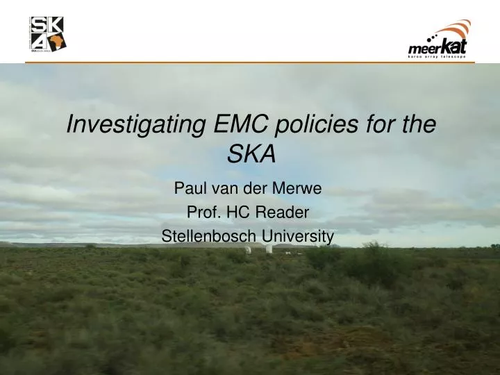
Investigating EMC policies for the SKA. Paul van der Merwe Prof. HC Reader Stellenbosch University. Introductory background. What was done during 2009? Cable tray measurements Pedestal interfaces Karoo site visit European visit investigating 2-PAD and EMBRACE aperture arrays.

E N D
Investigating EMC policies for the SKA Paul van der Merwe Prof. HC Reader Stellenbosch University
Introductory background What was done during 2009? • Cable tray measurements • Pedestal interfaces • Karoo site visit • European visit investigating 2-PAD and EMBRACE aperture arrays
Cable tray radiation measurements • Determine the shielding ability of cable trays in high frequency RFI environments. • Make use of known gain antennas and anechoic chamber. • S21 measured – induced voltage and gain calculated. • Define two methods using computational analysis.
Shielding analysis of cable trays: Method 1 • The cable tray structure is radiated using a plane wave definition with known E-field level. • Voltage induced on victim cable in cable tray measured at port.
Shielding analysis of cable trays: Method 2 • The cable tray structure is excited and far field radiation pattern is measured • Gain computed and compared to calculated gain using measured S21
Comparison: Measurement & Computation • Comparing measured and computed data validates the accuracy of the computational model. • Sequence have to be repeated for various positions of receiving antenna Method 1 Method 2
Pedestal interfaces: what can be done? • Power provision for dish needs to enter pedestal via some cable interface. • CM current on power cable able to enter pedestal. • Bonding of meshed floor to pedestal at point of entry reduces interference.
On-site measurements • Evaluate site RFI and interference generated by infrastructure. • Radiated interference measured – E-field antenna. • Conducted interference measured – CM current probe. • Proposed measurements on dish cables.
Investigating 2-PAD and EMBRACE: Purpose of visit • Exchange interaction between South African SKA effort and European aperture array development. • Become familiar with European SKADS, AAVP setup. • EMI investigations of both 2-PAD and EMBRACE systems. • Improve RFI mitigation for both systems. • Gain knowledge on aperture arrays – measurements experience 2-PAD EMBRACE
Power filter connected to transformer. Transformer supplies ground reference Test Points A/D converter Interface for cables with 360° connectors Ground plane Non-metallic sub-frame F Antenna elements I PC A D B C G EM Injection Clamp E Non-metallic support frame Suggested grounding points for chamber Ground Capacitive connection of ground plane to ground Equipotential bonding conductor Grounding schematic for array • Evaluation of induced CM current on system by radiated RFI. • Processing bunker shielding measurements • Transfer impedance measurements of different sections of system • Balun investigation
EMC chamber Signal generator Current probe LPDA Bunker shielding: How much does it protect? • Effective shielding of processing bunker important. • Bunker forms major part of RFI mitigation. • Effective diversion of CM current – Measurements conducted. • Validation of effective shielding at interfaces.
Signal source Signal source Antenna ground plane Antenna ground plane Antenna cable Antenna cable Bunker interface Circuitry inside bunker Capacitive coupling to ground Capacitive coupling to ground Bunker interface Circuitry inside bunker IDM ZL 75 Ω SA IDM ZL ICM Ztransfer Connector EM injection clamp EM injection clamp 75 Ω SA IDM Connector ICM ICM Ztransfer Vx VZt ICM ICM ICM ICM Vx VZt Ground SA SA Signal gen Signal gen Transfer impedance measurement • Transfer impedance: • Identify transfer impedances in EMBRACE grounding system. • Influence of transfer impedance can be approximated:
Finally • Shielding ability of cable trays at higher frequencies: can they be used? • Two methods defined two analyze them. • Improving the pedestal interfaces for cable entry. • Initial site evaluation of RFI. • Investigated 2-PAD and EMBRACE aperture array systems • Measured the induced CM currents, bunker shielding and transfer impedance.