Download
1 / 59
600 likes | 734 Views
LIGHT AND THE RETINAL IMAGE: KEY POINTS Light travels in (more or less) straight lines: the pinhole camera’s inverted image Enlarging the pinhole leads to BLUR How a lens prevents blur: refraction reunites light rays by bending them Point-to-point projection from object to inverted image

E N D
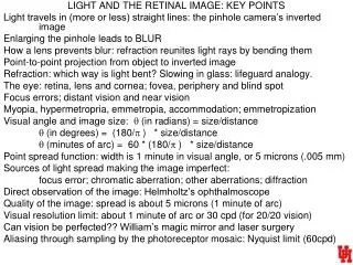
LIGHT AND THE RETINAL IMAGE: KEY POINTS Light travels in (more or less) straight lines: the pinhole camera’s inverted image Enlarging the pinhole leads to BLUR How a lens prevents blur: refraction reunites light rays by bending them Point-to-point projection from object to inverted image Refraction: which way is light bent? Slowing in glass: lifeguard analogy. The eye: retina, lens and cornea; fovea, periphery and blind spot Focus errors; distant vision and near vision Myopia, hypermetropria, emmetropia, accommodation; emmetropization Visual angle and image size: q (in radians) = size/distance q (in degrees) = (180/p ) * size/distance q (minutes of arc) = 60 * (180/p ) * size/distance Point spread function: width is 1 minute in visual angle, or 5 microns (.005 mm) Sources of light spread making the image imperfect: focus error; chromatic aberration; other aberrations; diffraction Direct observation of the image: Helmholtz’s ophthalmoscope Quality of the image: spread is about 5 microns (1 minute of arc) Visual resolution limit: about 1 minute of arc or 30 cpd (for 20/20 vision) Can vision be perfected?? William’s magic mirror and laser surgery Aliasing through sampling by the photoreceptor mosaic: Nyquist limit (60cpd)
A Review of Optics Austin Roorda, Ph.D. University of Houston College of Optometry
(Most of) these slides were prepared by Austin Roorda, (UC Berkeley Optometry School) and used by permission.
Geometrical Optics Relationships between pupil size, refractive error and blur
Optics of the eye: Depth of Focus 2 mm 4 mm 6 mm
Optics of the eye: Depth of Focus Focused behind retina In focus Focused in front of retina 2 mm 4 mm 6 mm
7 mm pupil Bigger blur circle Courtesy of RA Applegate
2 mm pupil Smaller blur circle Courtesy of RA Applegate
Demonstration Role of Pupil Size and Defocus on Retinal Blur Draw a cross like this one on a page, hold it so close that is it completely out of focus, then squint. You should see the horizontal line become clear. The line becomes clear because you have made you have used your eyelids to make your effective pupil size smaller, thereby reducing the blur due to defocus on the retina image. Only the horizontal line appears clear because you have only reduced the blur in the horizontal direction.
Physical Optics The Wavefront
What is the Wavefront? parallel beam = plane wavefront converging beam = spherical wavefront
What is the Wavefront? parallel beam = plane wavefront ideal wavefront defocused wavefront
What is the Wavefront? parallel beam = plane wavefront ideal wavefront aberrated beam = irregular wavefront
What is the Wavefront? diverging beam = spherical wavefront aberrated beam = irregular wavefront ideal wavefront
What is the Wave Aberration? diverging beam = spherical wavefront wave aberration
Wave Aberration of a Surface Wavefront Aberration 3 2 1 mm (superior-inferior) 0 -1 -2 -3 -3 -2 -1 0 1 2 3 mm (right-left)
Diffraction “Any deviation of light rays from a rectilinear path which cannot be interpreted as reflection or refraction” Sommerfeld, ~ 1894
Diffraction and Interference diffraction causes light to bend perpendicular to the direction of the diffracting edge interference due to the size of the aperture causes the diffracted light to have peaks and valleys
rectangular aperture square aperture
circular aperture Airy Disc
The Point Spread Function, or PSF, is the image that an optical system forms of a point source. The point source is the most fundamental object, and forms the basis for any complex object. The PSF is analogous to the Impulse Response Function in electronics.
The Point Spread Function The PSF for a perfect optical system is the Airy disc, which is the Fraunhofer diffraction pattern for a circular pupil. Airy Disc
As the pupil size gets larger, the Airy disc gets smaller. 2.5 2 1.5 separatrion between Airy disk peak and 1st min (minutes of arc 500 nm light) 1 0.5 0 1 2 3 4 5 6 7 8 pupil diameter (mm)
Point Spread Function vs. Pupil Size 1 mm 2 mm 3 mm 4 mm 5 mm 6 mm 7 mm
Small Pupil Little spreading due to defocus or aberrations So diffraction is limiting
Larger pupil: Less diffraction (not shown) But more blur and more aberrations
Point Spread Function vs. Pupil SizePerfect Eye (Diffraction Limited) 1 mm 2 mm 3 mm 4 mm 5 mm 6 mm 7 mm
Point Spread Function vs. Pupil SizeTypical Eye with aberrations 1 mm 2 mm 3 mm 4 mm pupil images followed by psfs for changing pupil size 5 mm 6 mm 7 mm
Demonstration Observe Your Own Point Spread Function
Unresolved point sources Rayleigh resolution limit Resolved
Keck telescope: (10 m reflector) About 4500 times better than the eye! “Pupil” is 10M: almost no diffraction Wainscott
Compound eye: • Each facet must be large to fight diffraction • Many facets (pixels) needed to capture details
Simulated Images 20/20 letters 20/40 letters
MTF Modulation Transfer Function
low medium high object: 100% contrast image 1 contrast 0 spatial frequency
The modulation transfer function (MTF) indicates the ability of an optical system to reproduce (transfer) various levels of detail (spatial frequencies) from the object to the image. • Its units are the ratio of image contrast over the object contrast as a function of spatial frequency. • It is the optical contribution to the contrast sensitivity function (CSF).
MTF: Cutoff Frequency cut-off frequency 1 mm 1 2 mm 4 mm Rule of thumb: cutoff frequency increases by ~30 c/d for each mm increase in pupil size 6 mm 8 mm modulation transfer 0.5 0 0 50 100 150 200 250 300 spatial frequency (c/deg)
Effect of Defocus on the MTF 450 nm 650 nm Charman and Jennings, 1976