Download
1 / 46
520 likes | 760 Views
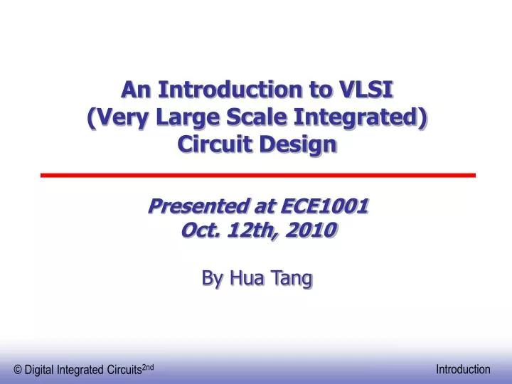
An Introduction to VLSI (Very Large Scale Integrated) Circuit Design. Presented at ECE1001 Oct. 12th, 2010 By Hua Tang. Basic IC circuit component: MOS transistor. MOS: Metal Oxide Semiconductor. First transistor Bell Labs, 1948. Intel 4004 Micro-Processor. 1971 1000 transistors

E N D
An Introduction to VLSI (Very Large Scale Integrated) Circuit Design Presented at ECE1001Oct. 12th, 2010 By Hua Tang
Basic IC circuit component: MOS transistor MOS: Metal Oxide Semiconductor First transistor Bell Labs, 1948
Intel 4004 Micro-Processor 1971 1000 transistors 1 MHz operation
Intel Pentium (IV) microprocessor 2002 35 Million transistors 1 GHz operation 0.18μm technology
Intel Core™2 Duo Processor 2006 >100 Million transistors 2 GHz operation 65nm technology
Intel Core™2 Quad Processor 2007 >800 Million transistors 2 GHz operation 45nm technology ( the biggest change in CMOS transistor technologies in 40 years) 2009 1 Billion transistors 3.3 GHz operation 23nm technology
Moore’s Law • In 1965, Gordon Moore noted that the number of transistors on a chip doubled every 18 to 24 months. • He made a prediction that semiconductor technology will double its effectiveness every 18 months
Moore’s law in Microprocessors Transistors on Lead Microprocessors double every 2 years 1000 2X growth in 1.96 years! 100 10 P6 Pentium® proc Transistors (MT) 486 1 386 0.1 286 8086 8085 0.01 8080 8008 4004 0.001 1970 1980 1990 2000 2010 Year Courtesy, Intel
Frequency 10000 Doubles every2 years 1000 P6 100 Pentium ® proc Frequency (Mhz) 486 386 10 8085 286 8086 8080 1 8008 4004 0.1 1970 1980 1990 2000 2010 Year Lead Microprocessors frequency doubles every 2 years Courtesy, Intel
Small Signal RF Power RF Power Management Analog Baseband Digital Baseband (DSP + MCU) Not Only Microprocessors Cell Phone HDTV PDA ….
Design Abstraction Levels SYSTEM MODULE + GATE CIRCUIT DEVICE G D S n+ n+
|V | GS A Switch! An MOS Transistor What is a MOS Transistor?
MOS Transistors - Types and Symbols D G S NMOS S G D PMOS
V DD V V in out C L The CMOS Inverter: A First Glance
V DD CMOS Inverter N Well PMOS 2l Contacts Out In Metal 1 Polysilicon NMOS GND
V V DD DD R p V =V out V =0 out R n V V V 0 = = in DD in CMOS InverterFirst-Order DC Analysis DD
V(y) V f OH V(y)=V(x) Switching Threshold V M V OL V(x) V V OL OH Nominal Voltage Levels DC OperationVoltage Transfer Characteristic VOH = f(VOL) VOL = f(VOH) VM = f(VM)
V out Slope = -1 V OH Slope = -1 V OL V V V IL IH in Mapping between analog and digital signals V “ 1 ” OH V IH Undefined Region V IL “ 0 ” V OL
Definition of Noise Margins "1" V OH Noise margin high NM H V IH UndefinedRegion V NM Noise margin low L IL V OL "0" Gate Input Gate Output
Transient Response The delay Essentially determines the clock speed of the processor tpHL tpLH
Static CMOS (Complementary MOS) VDD In1 PMOS only In2 PUN … InN F(In1,In2,…InN) In1 In2 PDN … NMOS only InN PUN and PDN are dual logic networks
NMOS Transistors in Series/Parallel Connection • Transistors can be thought as a switch controlled by its gate signal • NMOS switch closes when switch control input is high
The Ripple-Carry Adder Worst case delay linear with the number of bits td = O(N) tadder = (N-1)tcarry + tsum Goal: Make the fastest possible carry path circuit
Complimentary Static CMOS Full Adder 28 Transistors
Design Metrics • How to evaluate performance of a digital circuit (gate, block, …)? • Cost • Reliability • Scalability • Speed (delay, operating frequency) • Power dissipation • Energy to perform a function
Future Design Challenges • Processor architecture (multiple-core; interconnections) • Semi-conductor materials (current leakage; process variation) • Power consumption (power density; thermal dissipation)
Career in VLSI design VLSI circuit design and tool development • Intel • IBM • AMD • Cadence • Synopsys • MentorGraphics ....
VLSI Design: FFT Butterfly • Widely used in signal processing • Design Butterfly Unit for 2-point FFT • Components include multiplier, adder, subtractor, and data management 8-point FFT composed of 12 butterflies Image from www.cmlab.csie.ntu.edu.tw/cml/dsp/training/coding/transform/fft.html By: Spencer Strunic Matt Webb
VLSI Design: 8-bit CPU • Registers • Store data • Manipulate data • ALU • Select between many different operations to output • Adder • Adds two 8-bit numbers • Multiplier • Multiplies two 8-bit numbers By: Brian Linder Matt Leines
Viterbi Decoder • Cell phones • Dial-up modems • Satellite • Deep-space communications • 802.11 wireless LANS • Speech recognition systems • Magnetic disk drives • DNA research By: Scott Klar Bibhu Aryal Ryan Weidemann
Full Search Block Matching • Block Matching Algorithm (BMA): (1) popular motion estimation algorithm (2) key component of high-compression video codecs (3) used by several standards S S p p p n By: Zheng Yi Chang Hairong M M n p Reference block A Search area Motion vector Current frame (i+1) Previous frame (i)
FIR Filter By: Craig Bristow Joliot Chu FIR – Finite-Impulse Response Involves calculations of finite convolution sums in discrete-time systems Useful for Digital Signal Processing Equation - x is the input signal, h is the finite impulse response, y is the sum output and N is the order of the filter
FIR Filter System Design INPUT STORAGE CONTROL COEFFICIENTS STORAGE ARITHMETIC RESULTS STORAGE x[n]h[k]: Module 1 – Control Module Module 4 – Arithmetic Module Module 2 – Input Module Module 5 – Results Storage Module 3 – Coefficients Module
A Delta-Sigma Converter for WCDMA By: Matt Webb, Hairong Chang
A speech recognition system By: Peng Li
Contact Information: Office: MWAH 276 Hour: 2-4pm MW Phone: 726-7095 Email: htang@d.umn.edu Http: www.d.umn.edu/~htang
BMOW project (Big Mess of Wires) Material cost: $3,000 Build an CPU yourself?