Download
1 / 30
300 likes | 447 Views
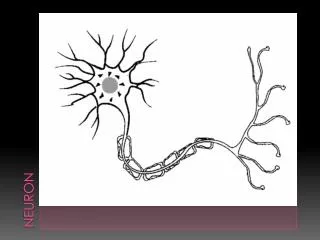
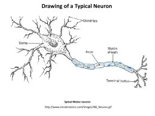
Building a VLSI Neuron. Brad Aimone, Stephen Larson and David Matthews BGGN 260 Project Winter, 2006. What is VLSI?. Very-Large-Scale Integrated Generating large circuits on a single chip by creating transistors Transistors are created by impurity doping Analog vs. Digital.

E N D
Building a VLSI Neuron Brad Aimone, Stephen Larson and David Matthews BGGN 260 Project Winter, 2006
What is VLSI? Very-Large-Scale Integrated • Generating large circuits on a single chip by creating transistors • Transistors are created by impurity doping • Analog vs. Digital
How VLSI works subthreshold courtesy Gert Cauwenberghs
Benefits of VLSI • Efficient modeling (using single transistors rather than software) allows on-line updating of parameters during real-time modeling • Inherent system noise • Involves biologically relevant constraints • available space (limited wiring) • power is at a premium • computations must be reliable and robust
Hodgkin-Huxley Model Graph of HH-Neuron from Matlab …where α’s & β’s are functions of voltage
Goals in designing a HH Neuron • For any given dynamical state {V,m,h,n} • System must calculate and apply instantaneous dynamics to calculate state variables • dV/dt = f(V,m,h,n); • dm/dt=f(a(V),b(V),m); … • Therefore, a(V), b(V)’s must be continuously calculated and fed into dm/dt, dn/dt, dh/dt
Practical considerations • Transmit information through circuit as voltages or currents? • Some math operations are easier in current, others easier in voltage • Currents can be ‘mirrored’ and reversed easily • Voltage operations are often more precise • In our system, most circuit subunits output information as current • Key state – Vneuron – is a voltage
Alpha/Beta Circuit • Need to fit unique HH equations for α and β for m,h,n • Input is Vneuron • Circuit should be general
Alpha/Beta Circuit • Can fit with “Bump Circuit” • Multiple “bumps” can be used to emulate α and β curves • Each has different Vreference and Ibias Picture of Bump Circuit Delbruck, 1991
Alpha/Beta Circuit • Bump circuit implemented • 4 bumps used to form circuit Simulations?
Alpha/Beta Circuit a_n Simulations? b_n
Alpha/Beta Integrator • Need to calculate dm/dt=B*m-A*(1-m) • Input is a’s and b’s • Output should be ‘m’,’h’, and ‘n’
Alpha/Beta Integrator • Need to calculate dm/dt=B*m-A*(1-m) • Input is a’s and b’s • Output should be current representing ‘m’,’h’, and ‘n’ Hynna & Boahen, 2006
Alpha/Beta Integrator • Need to calculate dm/dt=B*m-A*(1-m) • Input is a’s and b’s • Output should be current representing ‘m’,’h’, and ‘n’ Circuit diagram
Alpha/Beta Integrator Simulation
Multiplier circuit Need to combine m’s, h’s and n’s into m3h and n4
Multiplier circuit Need to combine m’s, h’s and n’s into m3h and n4 Can use translinear ‘floating gates’ to multiply currents Minch BA et al., 2001
Multiplier circuit Need to combine m’s, h’s and n’s into m3h and n4 Can use translinear ‘floating gates’ to multiply currents diode current charges to capacitors (relative weights are exponents) ‘Mirrored’ output current is a function of input currents and capacitive differences Minch BA et al., 2001
Multiplier circuit Our Circuit
Multiplier circuit Results / Simulation
Reversal Potential Scaling Current due to conductance and channel states (gNa*m3h and gK*n4)weighted by (ERev-V) Implemented by a “transconductance amplifier” Diagram of TCA
One whole channel a IK n n^4 B
K+ channel simulated n^4 IK
Na+ Channel m h I_Na m^3*h
Results & Conclusions • Designed and Implemented circuits to calculate • alphas and betas from voltage • m,h, and n from alphas and betas • multply m, h, and n’s; scale by conductances • reference currents to reversal potential and neuron voltage • Combine INa, IK, and ILeak to simulate neuron dynamics • Simulated and began to tune parameters to accurately model HH behavior
Future Directions • Solve remaining dynamical problems • Optimize bump circuit approximations • Generate more accurate a(v)’s and b(v)’s • Tune other parameters (gNa, gK, gLeak, capacitors) to optimize HH behavior • Work on layout of circuit on chip Special Thanks: Gert Cauwenberghs Jon Driscoll