Download
1 / 33
340 likes | 521 Views
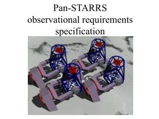
Pan-STARRS. Telescopes Four 1.8m R-C + corrector 7 square degree FOV Sited on Mauna Kea or Haleakala Operation mode Broad band optical imaging Four telescopes view the same field to detect transient or moving objects and build up a deep image of the sky Partners

E N D
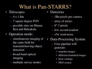
Telescopes Four 1.8m R-C + corrector 7 square degree FOV Sited on Mauna Kea or Haleakala Operation mode Broad band optical imaging Four telescopes view the same field to detect transient or moving objects and build up a deep image of the sky Partners IfA: science, detectors, pipelines MHPCC: production DP, infrastructure SAIC: databases and mass storage systems MIT-Lincoln Lab: detectors Detector and controllers 1.4x10⁹ 0.26” pixels per camera Image motion compensation 512 channel controller 3 second readout 5e- read-noise Data-Processing System Multicolor summed images Difference images for detection of moving and variable objects Catalogs of static, moving, transient objects Science “Killer Asteroids” (PHAs) Huge range of other science topics – presently imagination limited Pan-STARRS in a Nutshell
Observing Programs Science Programs Science Overview • Time domain astronomy • Transient objects • Moving objects • Variable objects • Static sky science • Enabled by stacking repeated scans to form a collection of ultra-deep static sky images • Very extensive overlaps between observational requirements of science programs!
Pan-STARRS Science Projects • Moving Object Science • NEO – Near Earth Object threat • OSS/MBO – Main Belt and Other Solar System science • KBO – Kuiper Belt Objects • SOL – Solar Neighborhood (parallaxes and proper motions) • Static and Invariable Object Science • WL – Weak Lensing • LSS – Large Scale Structure • LSB – Low Surface Brightness and dwarf galaxies • SPH – Spheroid formation • EGGS – Extragalactic and Galactic Stellar science • Transient and Variable Object Science • AGN – Active Galactic Nuclei • SNE – Supernovae • GRB – Gamma Ray Bursts and afterglows • EXO – Exoplanets (from occulation) • YSO – Young Stellar Objects • VAR – Variability Science (especially stars) • TGBN (Things that Go Bump in the Night)
Pan-STARRS Surveys • Solar System (Ecliptic Plane) – used primarily to satisfy the observing requirements imposed by the PHO, NEO, MBA, KBO and other SS programs. • 3 – used primarily to satisfy the observing requirements of the WL, LSN census, and EG object detection & classification programs; primary cadence drivers are the LSN census (and other proper motion studies) • Medium-Deep – the SNe, LSS, and the EG object detection & classification programs; primary cadence driver being SNe • Ultra-Deep – EG object detection & classification and, to some extent, SNe programs • Object Variability/Auxiliary – mostly user-defined supporting programs such as stellar variability and the search for extra-solar planets
Design Reference Mission 5- limit (AB) Total int. (min)
Final Data Products • Sky, the wallpaper: • 10 Tpix x 6 colors x N versions • Sky, the movie: • 10 Tpix x 6 colors x 50 epochs • Sky, the database: • 2x10¹⁰ objects (x 6 colors x 20-60 epochs) • Photometry to < 0.01 mag, astrometry to < 5 mas • Photometric redshifts of most of these objects • Identification and redshifts for all galaxy clusters • 109 proper motions (complete over 3) • 108 variable stars and AGN • 107 asteroids (104 NEO/PHA) • 107 transients (SN, GRB, etc.) • 3x10⁵ stars within 100 pc (with good parallax)
Pan-STARRS Optical Design 1” 1/3 arcsec
Pan-STARRS Focal Plane • Optics delivers a 3° field of view to meet science goals. • PSF sampling is 0.26” to optimize Mauna Kea seeing. • Therefore each focal plane will have 1.4 billion pixels. • Compared to existing cameras, goal is: • 10x the pixel count • 10x the readout speed • 0.1x the cost per pixel
Pan-STARRS 1 on Haleakala (Maui) PS1 First light in Jan 2006!
EOST Telescope Enclosure • Critical Design Review of enclosure completed. IceStorm Enclosure Levels Level 3 : Observing Floor Level 2 : Enclosure Maintenance Service Balcony Thermal barrier Insulated Stair to Level 3 Level 3 (Cart Rails) 8.2 m above grade Service balcony 8.2 m Level 2 5.6 m Access Balcony L 1 3 m External Access Stair Ground Level : Storage
Pan-STARRS4 on Mauna Kea CFHT UKIRT
Test Camera 3 (TC3) • TC3 is the stepping stone to GPC, allows us to test innovative technology and revise it for GPC: TC3 is almost an exact quarter GPC • Focal plane: SiC, curved, actuated? • Close packing of devices and controllers • CTI cryocoolers • Thermal management of focal plane • Implementation of wavefront sensors • First Light, TC3 will be used for First Light and early subsystem commissioning tasks • Populate with Lot 1 devices already in hand • Proceed with subsystem commissioning • TC3 provides excellent early testing of IPP • GPC1 will be deployed when the telescope is working more or less reliably.
Pan-STARRS will employ two WFS sensors “Deployable” Shack-Hartmann “Continuous” Curvature- sensing WFS Deployable WFS located in antechamber of camera extends out over focal plane to pick off a star for analysis Lenslet images and pupil images are parfocal with normal telescope images S-H sensor parked out of field of view for normal operations Wavefront Sensing (WFS)
Wavefront Sensors • Curvature sensing design • Four locations, above focal plane but outside 3 deg FOV • Converging lens and block of calcite • Two images of every star provide above and below focus donuts • Difference is quite sensitive to wavefront aberrations • Operates automatically and continuously with every exposure, no special pointing or overhead. • Results available within 30 sec.
GPC Architecture: DAQ3U and 2 OTAs • One Preamp + DAQ3U board runs 2 OTAs (16 channel) • 2 DAQ3U run a row of 4 OTAs • 4 DAQ3U (= 1 box) run a block of 8 OTAs • 4 box (= 1 camera side) • 2 Camera side = 1 GPC
Version 1 14 layer PCB 50 Ohm controlled impedance stackup Matched length on critical connections 672 and 74 ball BGAs 16 video channels Controller PCB Design
Focal plane consists of 4096 CCDs Any may be designated for rapid readout of guide stars All will have arbitrary OT shifting performed at 10 Hz Therefore want a CPU that is easy to program 300MHz PowerPC CPU in FPGA (LINUX ported) Xilinx Virtex2pro FPGA+HDL handles high speed real time functions Why the IOTA controller is different
Embedded memory • Huge number of pixels calls for on-controller memory and high data rates • Memory = 256MB of DDR ECC SDRAM per controller. Camera total 15 Gbytes.
Connectors – no Hand Wiring! • 64 devices, 4500 signals, and high speed drive the design • Cannot hand-wire, must match lengths and capacitances • Controller must live in same area as detectors • Cryo-flex assemblies connect directly to controller
Focal plane of 64 devices is 512 outputs; tiling and connections become very difficult if controller density is different from detector density Controller must have high density and low power, but ASICs are not mature yet. Use: 10MHz 16bit ADCs (AD9826) 32 channel 14bit DACs High Density – 512 channels/system
Data and control over ethernet for simplicity 1 Gigabit fiber required to keep up with data flow Standard ethernet switches lower cost of pixel servers, raises reliability. 100BT ethernet working (we saturate at 86Mbits/sec) TCP/IP and UDP tested and functional 1 G Ethernet tested at 200-400Mbit/s 1 Gigabit Ethernet Communications
Reset feedthru Serial feedthru Video 4 pedestal samples 3 pipeline (not necessary) 4 signal samples Multi-sampling (simple) Signal Chain • Preamp only offsets, filters and amplifies. • No dual slope integrator or clamp and sample • AC vs DC coupling • Negative substrate • 10-12MHz ADCs are multisampling to reduce read and ADC (3adu) noise, presently we sample during serial clocking transitions, but avoiding would be better.
Read Noise • Implemented MITLL sample during serial clocking • Read noise for reference low noise CCID20 • 3.5e- at 336kpixels/sec, multisample=4 • 4.1e- at 532kpixels/sec , multisample=4 • OTA total read time = ~5sec
Telescope Cameras Interface 1 Interface 7 Interface 6 Interface 2 Interface 3 Interface 4 Interface 5 Image Processing Pipeline Chip Level Chip Level Telescope and System Level System Level System Level System Level Image Capture Phase 0 Phase 4 Augmented Image Processing Phase 5 Science Client Product Generation Phase 6 Science Client Interfaces Phase 1 Detector Calibration (Calibration and Instrument Correction Processes) Phase 2 Map and Warp to Sky (Image Manipulation Processes) Phase 3 Create Sky Image (Image Combination Processes) Science Clients Scheduler Data Storage Data Storage Data Storage Data Storage Data Storage Data Storage TCS and Environment Monitoring Internal Product Generation Internal Product Generation NB: specifics have changed! Mission Planning…pre-staging of each night’s scheduling and supporting data…TBD
Data Volume • Expect 700 images = 10 Tb per night raw; 5 Tb per night adds up to >1 Pb per year reduced! • We have to be prepared not to “save the bits” • We must create a reliable enough pipeline that we tap all the science we want as the data flow through, and then throw away the raw data.
Development, infrastructure, and testing (2003-2005) Pan-STARRS1 (2006-2008) Pan-STARRS2 (2008+) Pan-STARRS3 Pan-STARRS4 Test Cameras 1-2 Test Camera 3 Gigapixel Camera 1 Gigapixel Camera 2 Gigapixel Camera 3 Gigapixel Camera 4 Pan-STARRS Development Schedule 90 Mpix 360 Mpix 1.4 Gpix 5.5 Gpix