Download
1 / 40
440 likes | 800 Views
PRINCIPLES OF MEASUREMENT AND INSTRUMENTATION EKT 112. Oscilloscope. Contents. The Basic Oscilloscope Beam Deflection Vertical Amplifier Horizontal Amplifier Sweep Generators. Introduction. The oscilloscope is basically a graph-displaying device – it draws a graph of an electrical signal.

E N D
PRINCIPLES OF MEASUREMENT AND INSTRUMENTATIONEKT 112 Oscilloscope
Contents • The Basic Oscilloscope • Beam Deflection • Vertical Amplifier • Horizontal Amplifier • Sweep Generators
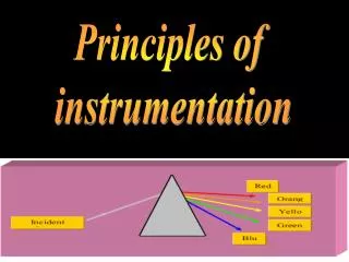
Introduction The oscilloscope is basically a graph-displaying device – it draws a graph of an electrical signal. The graph shows how signals change over time: Y - axis: represents voltage X - axis: represents time Z - axis: represents intensity or brightness (see Fig. 6.1)
Introduction…contd Figure 6.1: X, Y, and Z components of a displayed waveform
Introduction…contd This simple graph can tell you many things about a signal, such as: The time and voltage values of a signal. The frequency and phase. DC and AC components. Spectral analysis. Mathematical analysis. Rise and fall time. How much of the signal is noise and whether the noise is changing with time.
Contents • The Basic Oscilloscope • Beam Deflection • Vertical Amplifier • Horizontal Amplifier • Sweep Generators
Function of the various blocks • Cathode ray tube (CRT) - generates the electron beam, accelerates the beam to a high velocity, deflects the beam to create the image, and contains a phosphor screen where the electron beam eventually becomes visible. • Vertical Amplifier – wide band amplifier used to amplify signals in the vertical section.
Function of the various blocks…cont’d • Delay Line – used to delay the signal for some time in the vertical sections. • Time Base – used to generate the sawtooth voltage required to deflect the beam in the horizontal section. • Horizontal Amplifier – used to amplify the sawtooth voltage before it is applied to horizontal deflection plates.
Function of the various blocks…cont’d • Trigger circuit – used to convert the incoming signal into trigger pulses so that the input signal and the sweep frequency can be synchronized. • Power supply - Low voltage supply is required for the heater of the electron gun for generation of electron beam and high voltage, of the order of few thousand volts, is required for cathode ray tube to accelerate the beam. Normal voltage supply, say a few hundred volts, is required for other control circuits of the oscilloscope.
The Basic Oscilloscope A basic Oscilloscope is as shown below. Figure 6.2: Basic Oscilloscope
The Basic Oscilloscope The basic controls are: Brightness – to adjust the intensity of display. Focus – To adjust the focusing of display. Trigger – To select a trigger source. Trace – To select which trace is to be displayed. Timebase (sec/div)– To select the speed which the trace moves across the tube face. Input Level- To adjust the input level. Pos (Position) – To set the position of the trace on the display.
Contents • The Basic Oscilloscope • Beam Deflection • Vertical Amplifier • Horizontal Amplifier • Sweep Generators
Beam Deflection Figure 6.3: Basic construction of a CRT
Beam Deflection Cathode-ray tubes (CRT) used in oscilloscopes consist of an electron gun, a deflection system, and a fluorescent screen. The electron gun generates electrons and focuses them into a narrow beam. The deflection system moves the beam horizontally and vertically across the screen. The screen is coated with a phosphorous material that glows when struck by the electrons.
Beam Deflection The electron beam is developed, focused, and accelerated by the electron gun. The beam appears on the screen of the CRT as a small, bright dot. The beam of electrons passes through an electrostatic field between two plates. Electrons are negatively charged and that they will be deflected in the direction of the electric force (from negative to positive). This deflection causes the electrons to follow a curved path while in the electrostatic field.
Beam Deflection When the electrons leave the electrostatic field, they will take a straight path to the screen at the angle at which they left the field. The beam can be positioned anywhere on the screen by adjusting the controls marked horizontal position and vertical position. When the horizontal and vertical position controls are set to their midpoint position, the deflection voltages divide equally across both halves of the potentiometers. There is therefore no deflection of the beam; it simply travels along the axis of the CRT and strikes the centre of the screen.
Beam Deflection Adjusting the horizontal and vertical position control deflect the beam to any desired position on the screen. Factors influencing deflection angle: Length of the deflection field. Spacing between the deflection plates. The difference of potential between the plates. The accelerating voltage on the second anode.
Beam Deflection Length of the deflection field The longer deflection plates can bend the beam to a greater deflection angle.
Beam Deflection Spacing between the deflection plates The closer together the plates, the more effect the electric force has on the deflection angle of the electron beam.
Beam Deflection The difference of potential between the plates The greater the potential, the wider the deflection angle.
Beam Deflection The accelerating voltage on the second anode The faster the electrons are moving, the smaller their deflection angle will be.
Contents • The Basic Oscilloscope • Beam Deflection • Vertical Amplifier • Horizontal Amplifier • Sweep Generators
Vertical Amplifiers The vertical amplifier is the principal factor in determining the sensitivity and bandwidth of an oscilloscope. The gain of the vertical amplifier determines the smallest signal that the oscilloscope can be satisfactory reproduce on the CRT screen. The sensitivity of an oscilloscope is directly proportional to gain of the vertical amplifier; that is, as gain increases sensitivity increases, which allows us to observe smaller-amplitude signals.
Vertical Amplifiers The vertical sensitivity is a measure of how much the electron beam will be deflected for a specified input signal. Bandwidth of an oscilloscope determines the range of frequencies that can be accurately reproduced on the CRT screen. The greater the bandwidth, the wider the range of frequencies that can be observed with the instrument
Contents • The Basic Oscilloscope • Beam Deflection • Vertical Amplifier • Horizontal Amplifier • Sweep Generators
Horizontal Amplifiers The horizontal amplifier basically serves two purposes: When the oscilloscope is being used in the ordinary mode of operation to display a signal applied to the vertical input, the horizontal amplifier will amplify the sweep generator output. When the oscilloscope is being used in the X-Y mode, the signal applied to the horizontal input terminal will be amplified by the horizontal amplifier.
Contents • The Basic Oscilloscope • Beam Deflection • Vertical Amplifier • Horizontal Amplifier • Sweep Generators
Sweep Generators Oscilloscopes are used to display a waveform that varies as a function of time. If the waveform is to be accurately reproduced, the beam must have a constant velocity. Since the beam velocity is a function of the deflecting, voltage must increase linearity with time. A voltage with this characteristic is called a ramp voltage. If the voltage decreases rapidly to zero with waveform repeatedly reproduced, as shown in Figure 6.4, the pattern is generally called a sawtooth waveform.
Sweep Generators Figure 6.4: Typical sawtooth waveform applied to the horizontal deflection plates.
Sweep Generators During the sweep time, Ts the beam moves from left to right across the CRT screen. The beam is deflected to the right by the increasing amplitude of the ramp voltage and the fact that the positive voltage attracts the negative electrons. During retrace time, Tr the beam returns quickly to the left side of the screen. The control grid is generally “gated off”, which blanks out the beam during retrace and prevents an undesirable retrace pattern from appearing on the screen.
Applications of Oscilloscope Voltage Measurement Period and Frequency measurement
Volts/ div = • Time/div = • X10 probe = • Coupling = • Voltage = • Period = • Frequency=
CONTROL • Volts/ div = • Time/div = • X10 probe = • Coupling = • Voltage = • Period = • Frequency=
CONTROL • Volts/ div = • Time/div = • X10 probe = • Coupling = • Voltage = • Period = • Frequency=
CONTROL • Volts/ div = • Time/div = • X10 probe = • Coupling = • Voltage = • Period = • Frequency=
CONTROL • Volts/ div = • Time/div = • X10 probe = • Coupling = • Voltage = • Period = • Frequency=
Exercises • 1. If the horizontal sweep rate control is set to 0.1msec/Div, and a complete cycle of the sinewave occupies 7 divisions, what is the signal’s period? • 2. Suppose the vertical switch is set to 0.5V/div and a 10X scope probe is used. If the signal occupies 5 divisions vertically. • What is the peak to peak voltage? • If the time base is set to 2 msec/division and the period of signal is 6 msec. Sketch 3 cycles of sinewave signal.
CONTROL • Volts/ div = • Time/div = • X10 probe = • Coupling = • Voltage = • Period = • Frequency=