Download

1 / 31
310 likes | 458 Views
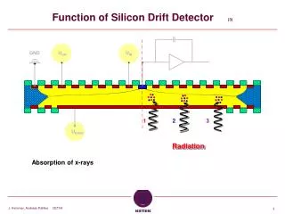
Operation of the ALICE Silicon Drift Detectors during cosmic data taking. Francesco Prino INFN – Sezione di Torino. RD09, Florence, September 30 th 2009. SDD sensor. 291 Drift cathodes. Voltage divider. Central Cathode at -HV. 120 m m pitch. 256x2 Anodes. E drift. v d (e - ).

E N D
Operation of the ALICE Silicon Drift Detectors during cosmic data taking Francesco Prino INFN – Sezione di Torino RD09, Florence, September 30th 2009
SDD sensor 291 Drift cathodes Voltage divider Central Cathode at -HV 120 mm pitch 256x2 Anodes Edrift vd (e-) HV, MV supply 294 mm pitch 70.2 mm vd (e-) Edrift Electron potential in SDD • LV supply • Commands • Trigger • Data Hybrid with front-end electronics (4 pairs of ASICs)
SDD Front-end electronics • PASCAL • Preamplifier • Analog Storage • Analog Memory sampled at 40 MHz (default) or 20 MHz • Conversion Analog->digitaL • 10 bit ADC • AMBRA • Digital multi-buffer • Anode-by-anode baseline equalization • Non-linear data compression • From 10 to 8 bit
SDD ladders and layers • CARLOS board • 8 inputs fed in parallel by 8 AMBRAs • 1 Carlos per SDD module • 2D 2-threshold zero suppression • Formats data and sends to DAQ
Cooling the SDD • Cooling agent: water • Pressure inside barrel <1 bar • Leak safe • Flow adjusted to stay in intermediate state between laminar and turbulent regime • Maximum heat exchange • 13 (sectors) * 2 (A/C side) *2 (Ladder/End-ladder)circuits with independent flow and pressure control • Safe operation controlled by dedicated Programmable Logic Controller: • Overpressure control to guarantee leak safety • Flow control to give the clearance for FEE operation.
SDD Detector Control System • Systems controlled by DCS: • LV power for Front-End Electronics • HV and MV supplies for SDD detectors • Cooling plant • State of readout cards • Finite States Machine (FSM) provides simple control of the whole system by well defined sequence of states • FSM communicates to DAQ and gives permission to start data-taking when detector is in ready state • Alarms and warnings logging system • Archiving of all system parameters • HV, MV, temperature recorded by thermistors …
Readout and DAQ Online Monitoring Layer 4/C • Each CARLOSrx board: • Uploads configuration to CARLOS/AMBRA/PASCAL (JTAG) • Sends trigger to CARLOS and busy to CTP • Reads data from up to 12 modules, apply data format compression and sends to DAQ 1 Global Data Concentrator Layer 4/A Layer 3 SDD: 260 modules DAQ control in Counting Room 24 CARLOSrx VME boards 6 Local Data Concentrators (PCs) Mass storage (CASTOR)
Running conditions Cathode 291 Edrift • Detector characteristics: • Readout and DAQ parameters • 245 (out of 260) modules stably in DAQ
Calibrating the SDD • Three SDD specific calibration runs collected every ≈24h to measure calibration parameters • Run Type: PEDESTAL • Analyzes special SDD calibration runs taken without zero suppression • Provides: Baselines, Noise, Common Mode Corrected Noise, Noisy anodes • Run Type: PULSER • Analyzes special SDD calibration runs taken with Test Pulse signal to front-end electronics • Provides: Anode gain, Dead anodes • Run Type: INJECTOR • Analyzes injector events collected every ≈ 10 min. during physics runs • Provides Drift speed (anode dependent) • A detector algorithm (DA) runs automatically at the end of each calibration run • Analyzes raw data and extracts relevant calibration quantities • Files with calibration parameters are stored in the Offline Condition DataBase and used in the offline reconstruction
Pedestal runs • Measure for each anode: • Baselines • Extract baseline equalization constants applied anode-by-anode in AMBRAs • Noise (raw and common mode corrected) Tag noisy anodes
Pedestal results vs. time (2008) Signal from MIP close to anodes ≈ 100 ADC counts
Pulserruns in 2008 AM sampling at 40 MHz • Measure gain for each anode sending Test Pulse to the input of front-end electronics • Used for anode-by-anode gain equalization in cluster finder AM sampling at 20 MHz Test Pulse Signal
Drift speed from injectors Display of 1 injector event on 1 drift side of 1 module • From INJECTOR runs (acquired every 24 hours) • 33x3 MOS charge injectors implemented in known positions on each drift side (half-module) • 33 determinations of drift speed along anode coordinate for each drift side • Drift speed extremely sensitive to temperature (T-2.4) • 0.8%/K variation at room temperature • Need 0.1% accuracy on drift speed to reach the design resolution of 35 mm along rf Drift speed on 1 drift side from fit to 3 injector points vdrift = mE T-2.4 Lower e- mobility / higher temperature on the edges
Drift speed vs. module • Drift speed (electron mobility) depends on: • Temperature • Higher drift speed on average on Layer 4 Lower temperature on layer 4 • Estimated temperatures ≈ 24C on Layer 3 and ≈ 21C on Layer 4 • Doping concentration (to a much lesser extent) • Resistivity: 3000-4000 cm Doping concentration ≈1.2-1.5 1012 cm-3 Layer 3 Layer 4
Drift speed stability – first test • Short term stability • Check stability during ≈ 1 hour, rate ≈ 2 triggers/minute • Fluctuations: r.m.s./mean ≈ 0.07% Tue, 04 Mar 2008 01:05:26 GMT Mon, 03 Mar 2008 23:51:32 GMT
Drift speed stability in 2008 • Long term stability • 3 months of data taking during summer 2008 • Drift speed stable within 0.2% Layer 3 off less heating Layer 3, Ladder 6, Mod 275, Anode 200 July 11th 2008 October 14th 2008 Layer 4, Ladder 14, Mod 428, Anode 200
SDD timing • Start-Of-Payload delay (= the number of clock-cycles after which the AM is frozen and read-out) • Tuned to accommodate the 5.4 ms of max. drift time into the 6.4 ms time window defined by the memory depth • Done with SOP delay scans during LHC injection tests with beam (bunches of 5 109 p at SPS energy) dumped close to ALICE
Analyses on cosmic data sample Talk by G. Aglieri • Statistics collected with SPD FastOr trigger: • 2008: ≈ 105 good cosmic tracks with full ITS, without B-field • Goal for 2009: ≈ 105 tracks with B-on + 105 tracks with B-off • Goals from analysis of cosmic data: • Align the 2198 ITS sensors with precision < than their resolution • Specific for SDD: calibrate the Time Zero • Time Zero = time after the trigger for a particle with zero drift distance • dE/dx calibration in SDD and SSD Statistics collected on Layer 4
Time Zero – method 1 • Cosmic track fitted in SPD and SSD layer • Track-to-point residuals along drift coordinate in the two drift regions of each SDD module • Show opposite signed peaks in case of mis-calibrated time zero • TimeZero = DeltaXlocal / 2. / vdrift = 434±6 ns • NOTE: preliminary value for 2009 data, averaged over all modules of layer 4 side A ALICE Preliminary ALICE Preliminary Xlocal residuals (cm) Xlocal residuals (cm)
Time Zero – method 2 • Extract TimeZero from the minimum measured drift time for SDD reconstructed points associated to tracks • PROS: no dependence on SDD calibration parameters (drift speed) • CONS: requires more statistics • First results from 2009 data analysis look promising • TimeZero from fit with error function of the rising edge = 434 ns (Layer 4 side A), BUT errors very large ALICE Preliminary
Geometrical alignment of SDD • Interplay between alignment and calibration • TimeZero for each module included as free parameter in Millepede-based alignment together with geometrical rotation and translation • Drift speed added as fit parameter for modules with mal-functioning injectors • Resolution along drift direction affected by the jitter of the SPD FastOR trigger (at 10 MHz 4 SDD time bins) with respect to the time when the muon crosses the SDD sensor Geometry only Geometry + calibration
Charge calibration (I) • Cluster charge distribution fitted with Landau+Gauss convolutions • Most Probable Value of collected charge depends on drift distance/time • Larger drift distance larger charge diffusion wider cluster tails cut by the zero suppression
Charge calibration (II) • Cross check with cosmics collected on few SDDs in test station with and without zero suppression • Data without zero suppression show no dependence of Landau MPV on drift time/distance • Apply linear correction of charge vs. drift time to cosmic data collected in 2008 by ALICE • Correction extracted from detailed MC simulations of SDD response
Conclusions • SDD successfully operated during ALICE cosmic data takings in 2008 and 2009 • 245 SDD modules (out of 260) stably in acquisition during both the data takings, fraction of good anodes > 97.5% • Calibration strategy deeply tested and tuned • Good knowledge of the detector reached • Noise level within the design goal (S/N for MIP close to anodes ≈ 50) • Drift speed stable with 0.2% during stable operation of ITS detectors • Results from cosmic data sampled allowed for • Develop tools for attacking the SDD alignment which is correlated with calibration quantities • Tuning of TimeZero module-by-module using Millepede • Recovering drift speed for modules with mal-functioning injectors • Calibrate the charge collection efficiency as a function of drift time • Good results by applying the correction based on MC simulation of Zero Suppression algorithm • SDD ready for the forthcoming p-p collisions at LHC
Inner Tracking System • Design goals • Optimal resolution for primary vertex and track impact parameter • Minimize distance of innermost layer from beam axis (<r>≈ 3.9 cm) and material budget • Maximum occupancy (central PbPb) < few % • 2D devices in all the layers • dE/dx information in the 4 outermost layers for particle ID in 1/b2 region
ITS Commissioning data taking TIME • Detector installation completed in June 2007 • Run 1 : December 2007 • First acquisition tests on a fraction of modules • Run 2 : Feb/Mar 2008 • ≈ 1/2 of the modules in acquisition due to cooling and power supply limitations • Calibration tests + first atmospheric muons seen in ITS • Installation of services completed in May 2008 • Run 3 : June/October 2008 • Subdetector specific calibration runs • Frequent monitoring of dead channels, noise, gain, drift speed … • Cosmic runs with SPD FastOR trigger • First alignment of the ITS modules + test TPC/ITS track matching • Absolute calibration of the charge signal in SDD and SSD • Run4 : started on mid August 2009
SDD correction maps • All the 260 SDD modules have undergone a complete characterization (map) before assembling in ladders • Charge injected with an infrared laser in > 100,000 known positions on the surface of the detector • For each laser shot, calculate residual between the reconstructed coordinate and the laser position along the drift direction • Systematic deviations due to: • Non-constant drift field due to non-linear voltage divider • Parasitic electric fields due to inhomogeneities in dopant concentration Ideal Module Non-linear volt. divider Dopant inhomogeneties
Drift speed vs. time Layer 3, Ladder 6, Mod 275, Anode 200 July 11th 2008 October 14th 2008
SDD during 2009 cosmic run • SDD constantly took cosmic data from Aug 17 to Sep 13 • 93% of modules included in DAQ • Fraction of good anodes in the good modules = 97% • <Event size> ≈ 10 kB / event (@ 20 MHZ AM sampling) • Factor 50 improvement w.r.t. 2008 Total number of anodes = 133120
ITS Alignment • Two track-based methods to extract the alignment objects (translations and rotations) for the 2198 ITS modules: • Millepede (default method, as for all LHC experiments) • Determine alignment parameters of “all” modules in one go, by minimizing the global c2 of track-to-points residuals for a large set of tracks • Iterative approach • Align one module at a time by fitting tracks in the other modules and minimizing the residuals in the module under study • Plus and hardware (based on collimated laser beams, mirrors and CCD cameras) alignment monitoring system • Monitor physical movements of ITS with respect to TPC • Strategy for the track-based alignment: • Use geometrical survey data as a starting point • Measurements of sensor positions on ladders during SDD and SSD construction • Hierarchical approach: • Start from SPD sectors (10) , then SPD half staves (120), then SPD sensors (240) • After fixing SPD, align SSD barrel (w.r.t. SPD barrel), then SSD ladders (72) … • After fixing SPD and SSD, move to SDD (which need longer time for calibration) • Include SDD calibration parameters: • Time Zero = time after the trigger for a particle with zero drift distance • Drift speed for modules with mal-functioning injectors