Download
1 / 55
550 likes | 671 Views
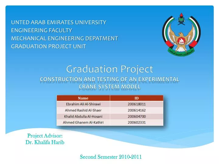
Graduation Project Construction and Testing of an Experimental Crane System Model. UNTED ARAB EMIRATES UNIVERSITY ENGINEERING FACULTY MECHANICAL ENGINEERING DEPATMENT GRADUATION PROJECT UNIT. Project Advisor: Dr. Khalifa Harib. Second Semester 2010-2011. Acknowledgments .

E N D
Graduation ProjectConstruction and Testing of an Experimental Crane System Model UNTED ARAB EMIRATES UNIVERSITY ENGINEERING FACULTY MECHANICAL ENGINEERING DEPATMENT GRADUATION PROJECT UNIT Project Advisor: Dr. Khalifa Harib Second Semester 2010-2011
Acknowledgments We would like to express our gratitude and appreciation to Abu Dhabi Water & Electricity Authority (ADWEA) for their generous support and funding our project. Moreover, we want to express our thanks to our advisor Dr. Khalifa Hareb for his continues help. In addition, we ant to thanks all engineers who help us during the graduation project. We want to thanks Dr. NayefGhasem, Dr. Kamal Mustafa and Dr. Farag Omar for serving as members of our final examination committee. Finally, we want to thank our families and our friends for their support.
Outline Project Description and Benefits Objectives and Goals Summary of GP1 Design Optimization Manufacturing Process and Results Economic, Ethical and contemporary issues Conclusions
Project Description and Benefits • Project Summary: • Design, construct and test a reduced size model of an overhead crane system. • The system implements a feedback closed loop control system and safety system. • This prototype will be used in control strategies for overhead cranes to control the swing and swing angles
Objectives and Goals • The project is divided into two phases. The first is related to graduation project I which has the following: • Developing overall design for overhead crane prototype • Designing each component with the necessary specifications, dimensions and tolerances to produce the final prototype • Selecting the materials to be used in the design • Analyze the overhead crane prototype in the dynamic mode • Selecting the appropriate motors and gearboxes for the prototype • Find a Sponsor for the project
Objectives and Goals • The objectives of graduation project II are: • Review the design parameters • Manufacturing the prototype • Purchasing mechanical and electrical components required to complete the design. • Designing a closed loop control system for the overhead crane prototype • Integrating the setup components to build the prototype • Testing and evaluating the setup performance
Summary of GP1 Design Process
Summary of GP1 • Crane arm • Triangular blocks with triangular truss segments made from aluminum angles • Size = 30cm height, 30 cm Width • Column Frame • Made from steel angles • Type of bearing used: taper bearing
Design Optimization • Improving the system • Reducing the size of: • The Crane Arm • Motors Required • Modifying the Crane Arm truss • A better Deflection Control • Complexity of manufacturing • Decrease the cost
Major Adjustments 20 x 20 cm 30 x 30 cm • Modifying the Crane Arm truss • From 30x30cm to 20x20cm
Major Adjustments • Modifying the Crane Arm truss • Removing unnecessary members • Round Tubes instead of Square Angles
Manufacturing Main Column • Reasons: • Extra Weight • No Value Added • Reduce the cost • Easy to manufacture • Allow more space for internal components assembly
Manufacturing Shaft • Manufacturing Features • Torque Transition through the junction • Lower Bearing Holding • Gear and Chain Connection • Bearing Seats
ManufacturingBearing Housing 4 Process Direction 3 2 1 • Assembly Procedure: • Holders • Lower Bearing Housing • Shaft • Upper Bearing Housing
ManufacturingCarriage • Criteria • Can hold a payload of 20 kg • Total weight of the carriage must be less than 20 kg • The carriage move on a rail attached to the crane arm • The transitional movement of the carriage is desired to be more than 1 m
ManufacturingCarriage E-Parts four parts Have been manufactured
ManufacturingCarriage Large Plate THE MAIN STRUCTURE OF THE CARRIAGE HOLDING THE E-PARTS
ManufacturingCarriage Small Plate WORKING AS A JUNCTION BETWEEN THE LARGE PLATE AND THE E-PART
ManufacturingCarriage Pulleys Holder CAPACITY OF HOLDING TWO PULLEYS
ManufacturingCarriage Wheels 12 WHEELS ARE REQUIRED EACH E-PART HAS 3 WHEELS
ManufacturingCarriage Pulleys TWO PULLEYS
ManufacturingCarriage Rails TWO RAILS MADE OF ALUMINUM BY CASTING
ManufacturingCarriage RAILS HOLDERS FOUR PIECES MAD OF ALUMINUM
Rails System • Keynotes: • Consist of two Aluminum Rails • The rails have been manufactured by casting • Four holders have been manufactured to hold the two rails. • The rails are fixed by bolts
Pulleys System • System Features • Two pulleys added on the upper arm round tube • Will be fixed by two pieces that surrounding the round tube • The two pieces are fixed by bolts • Two pulleys fixed with the carriage • Two pulleys at the middle of the arm
Motors & Gearboxes Motors has been selected with respect to required torque. Gearboxes selected to rise the motors torque to the required level
Real Control System Transfer function for Model 1 Θd1= n1 * φd Θd2= n2 * Xd Controller Θd1 τ1 Xd Feedback The Actual Results φd Controller Transfer function for Model 2 Θd2 τ1 Feedback
Control Function Arm motor transfer function equation in s domain is: • Carriage motor transfer function equation in s domain is:
PLC Design & Integration • PLC is a digital computer used for automation of electromechanical processes. • PLC type: SIEMENS S7-313C
PLC Design & Integration • Photo sensors • switches (emergency, reset and on/off button) • Electric Wires • Power Supply
PLC Design & Integration • Photo Sensors • Operates at a voltage of 24 DCV • NC type (Normally Close)
PLC Design & Integration • Photo Sensors
Contemporary Issues • Project Commercialization • The main objective is controlling the payload swinging which results in • Fast loading/unloading process • Time saving • Targeted Utilities • Harbors • Factories • Power Stations
Contemporary Issues • Existing problem in crane industry • Operator Safety • Working envelop • Solutions • Providing a control system to operate the crane from far distance