Download
1 / 29
290 likes | 450 Views
SRC Characteristics. (=) Load-store design: only way to access memory is through load and store instructions (–) Operation on 32-bit words only, no byte or half-word operations. (=) Only a few addressing modes are supported (=) ALU Instructions are 3-register type

E N D
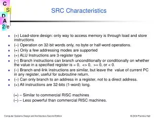
SRC Characteristics • (=) Load-store design: only way to access memory is through load and store instructions • (–) Operation on 32-bit words only, no byte or half-word operations. • (=) Only a few addressing modes are supported • (=) ALU Instructions are 3-register type • (–) Branch instructions can branch unconditionally or conditionally on whether the value in a specified register is = 0, <> 0, >= 0, or < 0. • (–) Branch-and-link instructions are similar, but leave the value of current PC in any register, useful for subroutine return. • (–) Can only branch to an address in a register, not to a direct address. • (=) All instructions are 32-bits (1-word) long. (=) – Similar to commercial RISC machines (–) – Less powerful than commercial RISC machines.
SRC Basic Instruction Formats • There are three basic instruction format types • The number of register specifier fields and length of the constant field vary • Other formats result from unused fields or parts • Details of formats:
I n s t r u c t i o n o p r a r b c 1 M e a n i n g A d d r e s s i n g M o d e l d r 1 , 3 2 1 1 0 3 2 D i r e c t R [ 1 ] M [ 3 2 ] l d r 2 2 , 2 4 ( r 4 ) 1 2 2 4 2 4 D i s p l a c e m e n t R [ 2 2 ] M [ 2 4 + R [ 4 ] ] s t r 4 , 0 ( r 9 ) 3 4 9 0 R e g i s t e r i n d i r e c t M [ R [ 9 ] ] R [ 4 ] l a r 7 , 3 2 5 7 0 3 2 I m m e d i a t e R [ 7 ] 3 2 l d r r 1 2 , - 4 8 2 1 2 – - 4 8 R e l a t i v e R [ 1 2 ] M [ P C - 4 8 ] l a r r 3 , 0 6 3 – 0 R e g i s t e r ( ! ) R [ 3 ] P C Tbl 2.4 Example Load & Store Instructions: Memory Addressing • Address can be constant, constant+register, or constant+PC • Memory contents or address itself can be loaded (note use of la to load a constant)
Assembly Language Forms of Arithmetic and Logic Instructions • Immediate subtract not needed since constant in addi may be negative Format Example Meaning neg ra, rc neg r1, r2 ;Negate (r1 = -r2) not ra, rc not r2, r3 ;Not (r2 = r3´ ) add ra, rb, rc add r2, r3, r4 ;2’s complement addition sub ra, rb, rc ;2’s complement subtraction and ra, rb, rc ;Logical and or ra, rb, rc ;Logical or addi ra, rb, c2 addi r1, r3, 1 ;Immediate 2’s complement add andi ra, rb, c2 ;Immediate logical and ori ra, rb, c2 ;Immediate logical or
Branch Instruction Format There are actually only two branch op codes: br rb, rc, c3<2..0> ;branch to R[rb] if R[rc] meets ; the condition defined by c3<2..0> brl ra, rb, rc, c3<2..0> ; R[ra] PC; branch as above • It is c3<2..0>, the 3 lsbs of c3, that governs what the branch condition is: lsbsconditionAssy language form Example 000 never brlnv brlnv r6 001 always br, brl br r5, brl r5 010 if rc = 0 brzr, brlzr brzr r2, r4 011 if rc 0 brnz, brlnz 100 if rc ≥ 0 brpl, brlpl 101 if rc < 0 brmi, brlmi • Note that branch target address is always in register R[rb]. • It must be placed there explicitly by a previous instruction.
Branch Instructions—Example C: goto Label3 SRC: lar r0, Label3 ; put branch target address into tgt reg. br r0 ; and branch • • • Label3 • • •
Example of conditional branch in C: #define Cost 125 if (X<0) then X = -X; in SRC: Cost .equ 125 ;define symbolic constant .org 1000 ;next word will be loaded at address 100010 X: .dw 1 ;reserve 1 word for variable X .org 5000 ;program will be loaded at location 500010 lar r31, Over ;load address of “false” jump location ld r1, X ;load value of X into r1 brpl r31, r1 ;branch to Else if r1≥0 neg r1, r1 ;negate value Over: • • • ;continue
RTN (Register Transfer Notation) • Provides a formal means of describing machine structure and function • Is at the “just right” level for machine descriptions • Does not replace hardware description languages. • Can be used to describe what a machine does (an Abstract RTN) without describing how the machine does it. • Can also be used to describe a particular hardware implementation (A Concrete RTN)
RTN Notation (Cont’d.) • At first you may find this “meta description” confusing, because it is a language that is used to describe a language. • You will find that developing a familiarity with RTN will aid greatly in your understanding of new machine design concepts. • We will describe RTN by using it to describe SRC.
Some RTN Features—Using RTN to describe a machine’s static properties Static Properties • Specifying registers • IR31..0 specifies a register named “IR” having 32 bits numbered 31 to 0 • “Naming” using the := naming operator: • op4..0 := IR31..27 specifies that the 5 msbs of IR be called op, with bits 4..0. • Notice that this does not create a new register, it just generates another name, or “alias” for an already existing register or part of a register.
Using RTN to describeDynamic Properties • Dynamic Properties • Conditional expressions: • (op=12) R[ra] R[rb] + R[rc]: ; defines the add instruction “if” condition “then” RTN Assignment Operator This fragment of RTN describes the SRC add instruction. It says, “when the op field of IR = 12, then store in the register specified by the ra field, the result of adding the register specified by the rb field to the register specified by the rc field.”
Using RTN to describe the SRC (static) Processor State • Processor state • PC31..0: program counter • (memory addr. of next inst.) • IR31..0: instruction register • Run: one bit run/halt indicator • Strt: start signal • R[0..31]31..0: general purpose registers
RTN Register Declarations • General register specifications shows some features of the notation • Describes a set of 32 32-bit registers with names R[0] to R[31] R[0..31]31..0: Colon separates statements with no ordering Name of registers Register # in square brackets msb # Bit # in angle brackets lsb# .. specifies a range of indices
Main memory state Mem[0..232 - 1]7..0: 232 addressable bytes of memory M[x]31..0 := Mem[x]#Mem[x+1]#Mem[x+2]#Mem[x+3]: Dummy parameter Naming operator Concatenation operator All bits in register if no bit index given Memory Declaration:RTN Naming Operator • Defining names with formal parameters is a powerful formatting tool • Used here to define word memory (big endian)
RTN Instruction Formatting Uses Renaming of IR Bits Instruction formats op4..0 := IR31..27: operation code field ra4..0 := IR26..22: target register field rb4..0 := IR21..17: operand, address index, or branch target register rc4..0 := IR16..12: second operand, conditional test, or shift count register c121..0 := IR21..0: long displacement field c216..0 := IR16..0: short displacement or immediate field c311..0 := IR11..0: count or modifier field
Specifying dynamic properties of SRC:RTN Gives Specifics of Address Calculation Effective address calculations (occur at runtime): disp31..0 := ((rb=0) c216..0 {sign extend}: displacement (rb0) R[rb] + c216..0 {sign extend, 2's comp.} ): address rel31..0 := PC31..0 + c121..0 {sign extend, 2’s comp.}: relative address • Renaming defines displacement and relative addrs. • New RTN notation is used • condition expression means if condition then expression • modifiers in { } describe type of arithmetic or how short numbers are extended to longer ones • arithmetic operators (+ - * / etc.) can be used in expressions • Register R[0] cannot be added to a displacement
Detailed Questions Answered by the RTN for Addresses • What set of memory cells can be addressed by direct addressing (displacement with rb=0) • If c216=0 (positive displacement) absolute addresses range from 00000000H to 0000FFFFH • If c216=1 (negative displacement) absolute addresses range from FFFF0000H to FFFFFFFFH • What range of memory addresses can be specified by a relative address • The largest positive value of C121..0 is 221-1 and its most negative value is -221, so addresses up to 221-1 forward and 221 backward from the current PC value can be specified • Note the difference between rb and R[rb]
Logical NOT Logical AND instruction_interpretation := ( RunStrt Run 1: Run (IR M[PC]: PC PC + 4; instruction_execution) ); Separates statements that occur in sequence Register transfer Instruction Interpretation: RTN Description of Fetch/Execute • Need to describe actions (not just declarations) • Some new notation
RTN Sequence and Clocking • In general, RTN statements separated by : take place during the same clock pulse • Statements separated by ; take place on successive clock pulses • This is not entirely accurate since some things written with one RTN statement can take several clocks to perform • More precise difference between : and ; • The order of execution of statements separated by : does not matter • If statements are separated by ; the one on the left must be complete before the one on the right starts
More about Instruction Interpretation RTN • In the expression IR M[PC]: PC PC + 4; which value of PC applies to M[PC] ? • The rule in RTN is that all right hand sides of “:” - separated RTs are evaluated before any LHS is changed • In logic design, this corresponds to “master-slave” operation of flip-flops • We see what happens when Run is true and when Run is false but Strt is true. What about the case of Run and Strt both false? • Since no action is specified for this case, the RTN implicitly says that no action occurs in this case
Individual Instructions • instruction_interpretation contained a forward reference to instruction_execution • instruction_execution is a long list of conditional operations • The condition is that the op code specifies a given inst. • The operation describes what that instruction does • Note that the operations of the instruction are done after (;) the instruction is put into IR and the PC has been advanced to the next inst.
RTN Instruction Execution for Load and Store Instructions • The in-line definition (:= op=1) saves writing a separate definition ld := op=1 for the ld mnemonic • The previous definitions of disp and rel are needed to understand all the details instruction_execution := ( ld (:= op= 1) R[ra] M[disp]: load register ldr (:= op= 2) R[ra] M[rel]: load register relative st (:= op= 3) M[disp] R[ra]: store register str (:= op= 4) M[rel] R[ra]: store register relative la (:= op= 5 ) R[ra] disp: load displacement address lar (:= op= 6) R[ra] rel: load relative address
SRC RTN—The Main Loop ii := instruction_interpretation: ie := instruction_execution : ii := ( RunStrt Run 1: Run (IR M[PC]: PC PC + 4; ie) ); ie := ( ld (:= op= 1) R[ra] M[disp]: Big switch ldr (:= op= 2) R[ra] M[rel]: statement . . . on the opcode stop (:= op= 31) Run 0: ); ii Thus ii and ie invoke each other, as coroutines.
Use of RTN Definitions:Text Substitution Semantics ld (:= op= 1) R[ra] M[disp]: • An example: • If IR = 00001 00101 00011 00000000000001011 • then ld R[5] M[ R[3] + 11 ]: disp31..0 := ((rb=0) c216..0 {sign extend}: (rb0) R[rb] + c216..0 {sign extend, 2's comp.} ): ld (:= op= 1) R[ra] M[ ((rb=0) c216..0 {sign extend}: (rb0) R[rb] + c216..0 {sign extend, 2's comp.} ): ]:
RTN Descriptions of SRC Branch Instructions • Branch condition determined by 3 lsbs of inst. • Link register (R[ra]) set to point to next inst. • cond := ( c32..0=0 0: never • c32..0=1 1: always • c32..0=2 R[rc]=0: if register is zero • c32..0=3 R[rc]0: if register is nonzero • c32..0=4 R[rc]31=0: if positive or zero • c32..0=5 R[rc]31=1 ): if negative • br (:= op= 8) (cond PC R[rb]): conditional branch • brl (:= op= 9) (R[ra] PC: • cond (PC R[rb]) ): branch and link
RTN for Arithmetic and Logic add (:= op=12) R[ra] R[rb] + R[rc]: addi (:= op=13) R[ra] R[rb] + c216..0 {2's comp. sign ext.}: sub (:= op=14) R[ra] R[rb] - R[rc]: neg (:= op=15) R[ra] -R[rc]: and (:= op=20) R[ra] R[rb] R[rc]: andi (:= op=21) R[ra] R[rb] c216..0 {sign extend}: or (:= op=22) R[ra] R[rb] R[rc]: ori (:= op=23) R[ra] R[rb] c216..0 {sign extend}: not (:= op=24) R[ra] R[rc]: • Logical operators: andor and not
RTN for Shift Instructions • Count may be 5 lsbs of a register or the instruction • Notation: @ - replication, # - concatenation n := ( (c34..0=0) R[rc]4..0: (c34..0≠0) c34..0 ): shr (:= op=26) R[ra]31..0 (n @ 0) # R[rb]31..n: shra (:= op=27) R[ra]31..0 (n @ R[rb]31) # R[rb]31..n: shl (:= op=28) R[ra]31..0 R[rb]31-n..0 # (n @ 0): shc (:= op=29) R[ra]31..0 R[rb]31-n..0 # R[rb]31..32-n: