Download
1 / 24
240 likes | 364 Views
=1.0. =1.5. =2.0. 1 2 3 4 5 6 FGT disks. FGT Layout Simulation Results. Detector requirements Disk layout e+/e- separation e/h discrimination Simu GEM response Strip layout, occupancy To-do- list Summary. Jan Balewski, MIT FGT Project Review

E N D
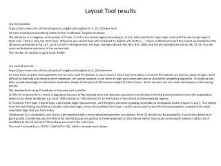
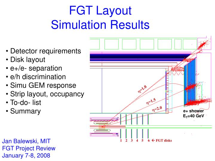
=1.0 =1.5 =2.0 1 2 3 4 5 6 FGT disks FGT Layout Simulation Results • Detector requirements • Disk layout • e+/e- separation • e/h discrimination • Simu GEM response • Strip layout, occupancy • To-do- list • Summary Jan Balewski, MIT FGT Project Review January 7-8, 2008 e+ shower ET=40 GeV
FGT Requirements • Reconstruct charge of e+, e- from W decay for PT up to 40 GeV/c • Discriminate electrons against hadrons • Allow for uniform performance for z-vertex spread over [-30,+30] cm • Fit in geometrical space free up by the West Forward TPC (FTPC) • Benefit from limited coverage of other trackers: IST, SSD • Relay on vertex reconstruction and Endcap shower-max hit • Relay on Endcap towers for energy reconstruction • Minimize amount of material on the path of tracks • Align FGT segmentation with TPC sector boundaries and Endcap halves • Assure relative alignment vs. TPC is double with real particles
Optimization of FGT Disks Location in Z a) Barrel EMC Used TPC volume nHits>=5 Endcap EMC =1.0 Zvertex=0cm =1.5 =2.0 SSD IST1,2 beam 1 2 3 4 5 6 R-‘unconstrained’ FGT disks Zvertex=+30cm Zvertex=-30cm c) b) 1 2 3 4 5 6 1 2 3 4 5 6 FGT disks geometry: Rin=7.5cm, Rout=41cm, Z1…Z6=60…150cm, Z=18cm • 5 hits required for helix reco • FGT sustains tracking if TPC provides below 5 hits • use TPC, SSD,IST for • Zvertex <~0 and <~1.3 • allow Zvertex[-30,+30]cm
Optimization of FGT Disk Radii (Z Vertex = 0 cm ) Endcap Used TPC volume nHits>=5 track = 1.7 =1.0 Zver=0cm =1.5 =2.0 TPC If nHit>5 Endcap SMD 1 2 3 4 5 6 FGT FGT 1 2 3 4 5 6 SSD IST1,2 vertex =1.7 Rxy – representation Rxy – Z representation • Optimization Criteria • Each track must cross the vertex and Endcap EMC • 6 FGT disk are needed to provide enough hits for tracks at all and all z-vertex • Single track crosses less than 6 FGT disks
Optimization of FGT Disk Radii (& location) 11.5 37.5 70 a) Z Vertex = - 30 cm b) Z Vertex = 0 cm c) Z Vertex = + 30 cm TPC If nHit>5 Endcap SMD FGT 1 2 3 4 5 6 SSD IST1,2 vertex FGT disks geometry: Rin=7.5cm, Rout=41cm, Z1…Z6=60…150cm, Z=18cm R-’unconstrained’ FGT disks FGT disks fitting in available R-space Critical FGT coverage depends on Z-vertex
FGT Enables Reco of Sign of e+,e- Sagitta (mm) Sagitta (mm) 2mm 2mm Endcap SMD hit =1.5mm Y/cm Good Q-sign Wrong Q-sign 100cm reco track 1 of reco track Sagitta=2mm Limit for pT track 40cm 3 FGT hits =70m 20cm X/mm Vertex =200m 1.0 2.0 mm 0
Track & Charge Sign Reco Efficiency FGT disks geometry: Rin=7.5cm, Rout=41cm, Z1…Z6=60…150cm, Z=18cm • N0 – thrown electrons, ET=30 GeV • N1 – reco tracks (<3 mrad) • N2 – reco tracks w/ correct charge sign • Track reco efficiency >80% for up to 2.0 • Wrong charge reco <20% for above 1.5
Stability of Charge Reconstruction Zvert=0 • Studied variations of efficiency (shown in proposal): • degraded FGT cluster resolution (80m 120m, OK) • reduced # of FGT planes (6 4 , bad, too few hits/track) • degraded transverse vertex accuracy (200m 500m, OK) • FGT cluster finding efficiency (100% 90%, OK , details) • smaller FGT disk size & separation - OK Rin=18cm, Rout=37.6cm, Z1…Z6=70…120cm, Z=10cm
e/h Discrimination Capability of Endcap EMC Pre Showers Shower Max Post Shower =2.0 30 GeV 0 GeV e+ =1.08 + GeV Simu of Endcap response to Electrons (black) & charge pions (red) with ET of 30 GeV e+ + Endcap + e+ Projective tower Shower from electron E=30 GeV ~15 GeV ET Trigger threshold
e/h Discrimination : PYTHIA Events Isolation & missing-PT cuts suppress hadrons by ~100 Hadrons from PYTHIA M-C QCD events e+, e- from PYTHIA M-C W-events
Real Electrons Reconstructed in Endcap Endcap-based cuts TPC P [6,8] GeV/c TPC P [10,14] GeV/c e+, e- • MIP e+, e- • MIP Identified e+,e-
Detailed Simulation of GEM Response (1) Latice attractors spaced 130 m Charge from this hexagon is attracted by the hole Hole in GEM foil amplifies charge cloud Primary ionization R-axis strip Pitch=800m xhit phi-axis strip pitch=600m Amplified signal is displaced best • ionization and charge amplification • spatial quantization on GEM grid • charge collection by strip planes • 1D cluster reconstruction
Simulated FGT Response (2) 14 prim pairs/track 14 prim pairs/track 22 eV/pair 22 eV/pair (760 eV/ track) R* =40m 32 any pairs/track R=122m GEM response Test beam data 1D Cluster finder resolution
FGT Strip Layout *) y x y x 326 R-strips X z 15 deg Endcap halves Top -layer 949 -strips pitch 600m Essential for PT reco ~ 50% transparency FGT quadrant boundaries match to Endcap segmentation Bottom R-layer pitch 800m needed for 3D track recognition, resolving ambiguities *) close to final
Estimation of Strip Occupancy tracks 2 1 1 -strips 400 m pitch R-strips 45 deg long 0 1 track/strip per 1000 minB events tracks Track rate per strip for minB PYTHIA events @ s500 GeV Based on FGT geometry:Rin=15cm, Rout=41cm R=41cm R=15cm 0.8 0.4 0 =0 deg =90 • pileup from minB events dominates • 1.5 minB interactions/RHIC bXing • 300nsec response of APV • 3 bXings pile up • Total pileup of 5 minB events per trigger event • 1 tracks per FGT quadrant per minB event • (scaled from simu below) • Cluster size: 1mm along , 2mm along R • Cluster occupancy per triggered event per quadrant • -strips (span ~43cm)1.2% occupancy • R-strips (span 25cm) 4% occupancy • (uncertainty factor of 2) minB PYTHIA event @ s=500 GeV
To-do List • completion of detailed (a.k.a. ‘slow’) simulator for GEM response • develop 3D tracking with pattern recognition • include pileup from 3 events in reco of physics events • implement and optimize full array of e/h discrimination techniques • completion of full W event simulation and comparison to full hadronic QCD events simulation • determine background contribution from Z0 and heavy flavor processes, above pT>20 GeV/c
FGT Simulation Summary • Will be able to reconstruct charge of e+, e- from W decay for PT up to 40 GeV/c with efficiency above 80% • There is enough information recorded to discriminate electrons against hadrons • Allow for uniform performance for z-vertex spread over [-30,+30] cm, OK • Will fit in geometrical space • Will use hits from IST, SSD • Will relay on vertex reconstruction and Endcap shower-max hit & energy • FGT quadrants are aligned with TPC sector boundaries and Endcap halves • FGT disks 1 &2 overlap with TPC allowing relative calibration
Compact FGT- proof of principle Rin=18cm, Rout=37.6cm, Z1=70cm, …,Z6=120cm, Z=10 cm Critical FGT coverage depends on Z-vertex
FGT Material budget UPGR13, maxR=45 cm 0.5 Z vert= - 30cm Z vert= 0cm Z vert= + 30cm 0 0.5 0
TPC reco with 5 points ‘regular’ tracking 5-hits tracking ‘regular’ tracking 5-hits tracking
Alternative Snow-flake Strip Layout 12-fold local Cartesian ref frame As in Proposal
Track Reco Strategy 1 2 3 4 5 6 FGT • Select EMC cluster with large energy • Eliminate all FGT hits outside the cone: vertex SMD hit • Resolve remaining ambiguities comparing R vs. charge • Consider shorter -strips (snow flake design) 3 4 1 2