Download
1 / 15
170 likes | 378 Views
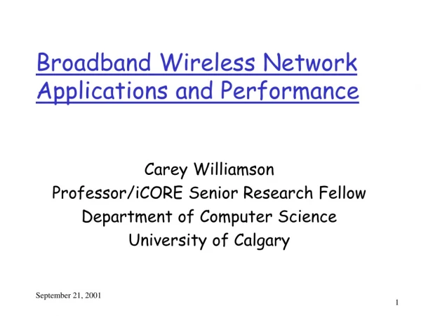
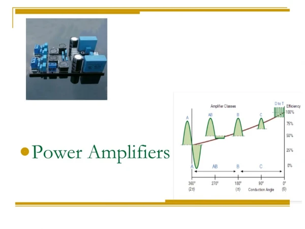
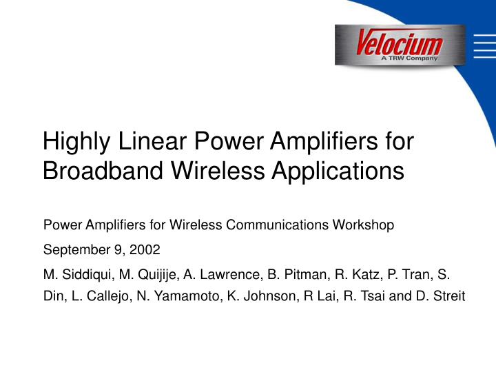
Power Amplifiers for Wireless Communications Workshop September 9, 2002 M. Siddiqui, M. Quijije, A. Lawrence, B. Pitman, R. Katz, P. Tran, S. Din, L. Callejo, N. Yamamoto, K. Johnson, R Lai, R. Tsai and D. Streit. Highly Linear Power Amplifiers for Broadband Wireless Applications.

E N D
Power Amplifiers for Wireless Communications Workshop September 9, 2002 M. Siddiqui, M. Quijije, A. Lawrence, B. Pitman, R. Katz, P. Tran, S. Din, L. Callejo, N. Yamamoto, K. Johnson, R Lai, R. Tsai and D. Streit Highly Linear Power Amplifiers for Broadband Wireless Applications
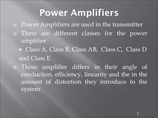
Applications Landscape • Higher data rates dictate highly linear transmit chains • Major contributor to linearity and cost is the driver / power amplifier combination.
TRW Pseudomorphic HEMT Process • 0.15 um T-gate process • Breakdown > 8 Volts • fT > 85 GHz at Vds > 4 volts • Gm> 500 mS/mm • Imax> 500 mA/mm • 4mil substrate thickness • Flight qualified, commercially proven process S ource D rain G ate + n -GaAs undoped AlGaAs Si plane doping undoped InGaAs undoped AlGaAs GaAs substrate
TRW 0.15mm PHEMT Process Reliability • Ea »1.6 eV, Sigma = 0.6 • MTF » 6X10¹⁰ hours at Tj=125oC Ta=210C Ta=235C Ta=250C Ta=265C Typical benchmark, 1X10⁶ hrs at 125BC
Summary of Circuit Performance State of the art output power density enables smaller die size and less DC power dissipation
37 to 40 GHz Power Amplifier APH473 Die Size = 4.5 mm2 Power Density @ P1dB = 400 mW/mm Power Density @ P3dB = 582 mW/mm
37 to 40 GHz Power Amplifier Performance vs. DC Bias
37 to 40 GHz Power Amplifier Performance vs. Temperature Gain Yield at 38.5 GHz
40 to 44 GHz Power Amplifier APH474 Die Size = 4.25 mm2 Power Density @ P1dB = 400 mW/mm Power Density @ P3dB = 582 mW/mm
17 to 20 GHz Power Amplifier APH478 Die Size = 5.02 mm2 Power Density @ P1dB = 446 mW/mm Power Density @ P3dB = 588 mW/mm
28 to 31 GHz Driver Amplifier APH496 Die Size = 2.61 mm2 Power Density @ P1dB = 443 mW/mm Power Density @ P3dB = 584 mW/mm
29 to 32 GHz Power Cell Power Cell Die Size = 1.86 mm2 Power Density @ P1dB = 436 mW/mm Power Density @ P3dB = 588 mW/mm
32 to 35 GHz Driver Amplifier APH497 Die Size = 2.61 mm2 Power Density @ P1dB = 414 mW/mm Power Density @ P3dB = 584 mW/mm
34 to 36 GHz Power Amplifier APH502 Die Size = 3.55 mm2 Power Density @ P1dB = 519 mW/mm Power Density @ P3dB = 588 mW/mm
Conclusion • Higher data rates dictate a need for highly linear transmit chains. • A major contributor to linearity and cost is the driver / power amplifier combination. • Maximizing the output power density in the driver / power amplifier chain enables reduced die size and DC power consumption. • Velocium’s PA MMICs have shown state of the art linearity and power density in a production process.