Download
1 / 65
650 likes | 672 Views
Get an in-depth perspective of operating systems design and learn about the virtual machine and resource management. Explore the history of computers and the fundamentals of machine organization. Discover the fetch-decode-execute loop and how instructions are encoded. Gain insights into memory indirection, conditionals, and looping.

E N D
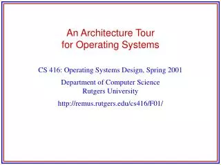
An Architecture Tour for Operating Systems CS 6560: Operating Systems Design
Content • View of a computer from an OS designer perspective • Operating system is a layer of software that creates a virtual machine and manages the resources of this machine • The following lectures will familiarize you with • The underlying machine (a very simplified version of it) • The extra hardware mechanisms needed for virtualization
von Neumann Machine • The first computers (late 40’s) were calculators • The advance was the idea of storing the instructions (coded as numbers) along with the data in the same memory • Crux of the split between: • Central Processing Unit (CPU) and • Memory
Memory contents 0 CPU 1 2 + - * / 3 4 5 6 7 8 9 Conceptual Model Addresses of memory cells "big byte array"
Operating System Perspective • A computer is a piece of hardware which runs a fetch-decode-execute loop • Next slides: walk through a very simple computer to illustrate • Machine organization • What the pieces are and how they fit together • The basic fetch-decode-execute loop • How higher level constructs are translated into machine instructions
Fetch-Decode-Execute • Computer as a large, general-purpose calculator • Want to program it for multiple functions • All von Neumann computers follow the same loop: Fetch the next instruction from memory Decode the instruction to figure out what to do Execute the instruction and store the result • Instructions are simple. Examples: • Increment the value of a memory cell by 1 • Add the contents of memory cells X and Y and store in Z • Multiply contents of memory cells A and B and store in B
Instruction Encoding • How to represent instructions as numbers? 8 bits 8 bits 8 bits 8 bits operators +: 1 -: 2 *: 3 /: 4 operands destination
Example Encoding • Add cell 28 to cell 63 and place result in cell 100: 8 bits 8 bits 8 bits 8 bits operator +: 1 -: 2 *: 3 /: 4 source operands destination Cell 28 Cell 63 Cell 100 Instruction as a number in: Decimal: 1:28:63:100 Binary: 00000001:00011100:00111111:01100100 Hexadecimal: 01:1C:3F:64
Example Encoding (cont) • How many instructions can this encoding have? • 8 bits, 2^8 combinations = 256 instructions • How much memory can this example instruction set support? • Assume each memory cell is a byte (8 bits) wide • Assume operands and destination come from the same memory • 8 bits per source/dest = 2^8 combinations = 256 bytes • How many bytes did we use per instruction? • 4 bytes per instruction
The Program Counter • Where is the “next instruction” held in the machine? • A special memory cell in the CPU, called the “program counter" (or simply, the PC), contains the address of the next instruction • Special purpose memory in the CPU and devices are called registers • Naïve fetch cycle: Increment the PC by the instruction length (4) after each execute • Assumes all instructions are the same length
Memory 0 operator 1 operand 1 2 operand 2 3 destination 4 5 6 7 8 9 Conceptual Model Instruction 0 @ memory address 0 CPU + - * / Arithmetic Units Instruction 1 @ memory address 4 Program Counter 4
Memory Indirection • How do we access array elements efficiently if all we can do is name a cell? • Modify the operand to allow for fetching an operand "through" a memory location • E.g.: LOAD [5], 2 means fetch the contents of the cell whose address is in cell 5 and put it into cell 2 • So if cell 5 had the number 100, we would place the contents of cell 100 into cell 2 • This is called indirection • Fetch the contents of the cell “pointed to” by the cell in the opcode • Steal an operand bit to signify if an indirection is desired
Conditionals and Looping • Primitive “computers” only followed linear instructions • Breakthrough in early computing was addition of conditionals and branching • Instructions that modify the Program Counter • Conditional instructions • If the content of this cell is [positive, not zero, etc.] execute the instruction or not • Branch Instructions • If the content of this cell is [zero, non zero, etc.], set the PC to this location • jump is an unconditional branch
Example: While Loop Variables to memory cells: counter is cell 1 sum is cell 2 index is cell 3 Y[0]= cell 4, Y[1]=cell 5… • while (counter > 0) { • sum = sum + Y[counter]; • counter–-; • }; Memory cell address Assembler label Assembler "mnemonic" English • 100 LOOP: BZ 1,END // Branch to address of END • // if cell 1 is 0. • 104 ADD 2,[3],2 // Add cell 2 and the value • // of the cell pointed to by • // cell 3 then place the • // result in cell 2 • 108 DEC 3 // Decrement cell 3 by 1 • 112 DEC 1 // Decrement cell 1 by 1 • 116 JUMP LOOP // Start executing from the • // address of LOOP • 120 END: <next code block>
Registers • Architecture rule: large memories are slow, small ones are fast • But everyone wants more memory! • Solution: Put small amount of memory in the CPU for faster operation • Most programs work on only small chunks of memory in a given time period. This is called locality. • So, if we cache the contents of a small number of memory cells in the CPU memory, we might be able to execute many instructions before having to access memory • Small memory in CPU named separately in the instructions from the “main memory” • Small memory in CPU = registers • Large memory = main memory
Register Machine Model Memory 0 CPU 1 +,-,*,/ Arithmetic Units 2 3 Logic Units <,>,!= 4 Program Counter 8 5 6 register 0 24 7 register 1 100 8 9 register 2 18
Registers (cont) • Most CPUs have 16-32 “general purpose” registers • All look the “same”: combination of operators, operands and destinations possible • Operands and destination can be in: • Registers only (Sparc, PowerPC, Mips, Alpha) • Registers & 1 memory operand (Intel x86 and clones) • Any combination of registers and memory (Vax) • Only memory operations possible in "register-only" machines are load from and store to memory • Operations 100-1000 times faster when operands are in registers compared to when they are in memory • Save instruction space too • Only address 16-32 registers, not GB of memory
Typical Instructions • Add the contents of register 2 and register 3 and place result in register 5 • ADD r2,r3,r5 • Add 100 to the PC if register 2 is not zero • Relative branch • BNZ r2,100 • Load the contents of memory location whose address is in register 5 into register 6 • LDI r5,r6
Abstracting the Machine • Bare hardware provides a computation device • How to share this expensive piece of equipment between multiple users? • Sign up during certain hours? • Give program to an operator? • they run it and give you the results • Software to give the illusion of having it all to yourself while actually sharing it with others! • This software is the Operating System • Need hardware support to “virtualize” machine
Architecture Features for the OS • Next we'll look at the mechanisms the hardware designers add to allow OS designers to abstract the basic machine in software • Processor modes • Exceptions • Traps • Interrupts • These require modifications to the basic fetch-decode-execute cycle in hardware
Processor Modes • OS code is stored in memory … von Neumann model, remember? • What if a user program modifies OS code or data? • Introduce modes of operation • Instructions can be executed in user mode or system mode • A special register holds which mode the CPU is in • Certain instructions can only be executed when in system mode • Likewise, certain memory locations can only be written when in system mode • Only OS code is executed in system mode • Only OS can modify its memory • The mode register can only be modified in system mode
Simple Protection Scheme • All addresses < 100 are reserved for operating system use • Mode register provided • zero = SYS = CPU is executing the OS (in system mode) • one = USR = CPU is executing in user mode • Hardware does this check: • On every fetch, if the mode bit is USR and the instruction address is less than 100, then do not execute the instruction • When accessing operands, if the mode bit is USR and the operand address is less than 100, do not execute the instruction • Mode register can only be set if mode is SYS
99 100 101 102 103 104 105 106 Simple Protection Model CPU Memory +,-,*,/ 0 Arithmetic Units Logic Units <,>,!= OS Program Counter 8 User Registers 0-31 Mode register 0
Fetch-decode-execute Revised • Fetch: • if ((PC < 100) && (mode register == USR)) then • Error! User tried to access the OS • else • fetch the instruction at the PC • Decode: • if ((destination register == mode) && (mode register == USR)) then • Error! User tried to set the mode register • < more decoding > • Execute: • if ((an operand < 100) && (mode register == USR) then • Error! User tried to access the OS • else • execute the instruction
Exceptions • What happens when a user program tries to access memory holding the operating system code or data? • Answer: exceptions • An exception occurs when the CPU encounters an instruction which cannot be executed • Modify fetch-decode-execute loop to jump to a known location in the OS when an exception happens • Different errors jump to different places in the OS (are "vectored" in OS speak)
Fetch-decode-execute with Exceptions • Fetch: • if ((PC < 100) && (mode register == USR)) then • set the PC = 60 • set the mode = SYS • fetch the instruction at the PC • Decode: • if ((destination register == mode) && (mode register == USR)) then • set the PC = 64 • set the mode = SYS • goto fetch • < more decoding > • Execute: • < check the operands for a violation > 60 is the well- known entry point for a memory violation 64 is the well- known entry point for a mode register violation
Access Violations • Notice both instruction fetch from memory and data access must be checked • Execute phase must check both operands • Execute phase must check again when performing an indirect load • This is a very primitive memory protection scheme. We'll cover more complex virtual memory mechanisms and policies later in the course
Recovering from Exceptions • The OS can figure out what caused the exception from the entry point • But how can it figure out where in the user program the problem was? • Solution: add another register, the PC’ • When an exception occurs, save the current PC to PC’ before loading the PC with a new value • OS can examine the PC' and perform some recovery action • Stop user program and print an error message: error at address PC' • Run a debugger
Fetch-decode-execute with Exceptions & Recovery • Fetch: • if ((PC < 100) && (mode register == USR)) then • set the PC' = PC • set the PC = 60 • set the mode = SYS • fetch instruction at the PC • Decode: • if ((destination register == mode) && (mode register == USR)) then • set the PC' = PC • set the PC = 64 • set the mode = SYS • goto fetch • < more decoding > • Execute: • …
Traps • Now we know what happens when a user program illegally tries to access OS code or data • How does a user program legitimately access OS services? • Solution: Trap instruction • A trap is a special instruction that forces the PC to a known address and sets the mode into system mode • Unlike exceptions, traps carry some arguments to the OS • Foundation of the system call
Fetch-decode-execute with Traps • Fetch: • if ((PC < 100) && (mode register == USR)) then • < memory exception > • Decode: • if (instruction is a trap) then • set the PC' = PC • set the PC = 68 • set the mode = SYS • goto fetch • if ((destination register == mode) && (mode register == USR)) then • < mode exception > • Execute: • …
Traps • How does the OS know which service the user program wants to invoke on a trap? • User program passes to the OS a number that encodes which OS service is desired • This example machine could include the trap ID in the instruction itself: • Most real CPUs have a convention for passing the trap ID in a set of registers • E.g. the user program sets register 0 with the trap ID, then executes the trap instruction Trap opcode Trap service ID
Returning from a Trap • How to "get back" to user mode and the user's code after a trap? Could we use two instructions? • Set the mode register = 1 then set the PC? • But after the mode bit is set to user, exception! • Set the PC, then set the mode bit? • Jump to "user-land", then in kernel mode • Most machines have a "return from exception" instruction • A single hardware instruction: • Sets the PC to PC' • Sets the mode bit to user mode • Traps and exceptions use the same mechanism (RTE)
Fetch-decode-execute with Traps • Fetch: • if ((PC < 100) && (mode register == USR)) then • < memory exception > • Decode: • if (instruction is RTE) then • set the PC = PC' • set the mode = USR • goto fetch • if ((destination register == mode) && (mode register == USR)) then • < mode exception > • Execute: • …
Interrupts • How can we force the CPU back into system mode if the user program is off computing something? • Solution: Interrupts • An interrupt is an external event that causes the CPU to jump to a known address • For now, let’s link an interrupt to a periodic clock (there are other types of interrupts as well. Any idea?) • Modify fetch-decode-execute loop to check an external line set periodically by the clock
Simple Interrupt Model CPU Memory +,-,*,/ OS Arithmetic Units User Logic Units <,>,!= Program Counter 8 Interrupt line PC' Clock Registers 0-31 Reset line Mode register 0
The Clock • The clock starts counting to 10 milliseconds • When the 10 milliseconds elapse, the clock sets the interrupt line "high" • When the CPU toggles the reset line, the clock sets the interrupt line low and starts count to 10 milliseconds again
Fetch-decode-execute with Interrupts • Fetch: • if (clock interrupt line == 1) then • set the PC' = PC • set the PC = 72 • set the mode = SYS • goto fetch • if ((PC < 100) && (mode register == USR)) then • < memory exception > • fetch next instruction • Decode: • if (instruction is a trap) then • < trap exception > • if ((destination register == mode) && (mode register == USR)) then • < mode exception > • < more decoding > • Execute: …
Entry Points • What are the "entry points" for our little example machine? • 60: Memory access violation • 64: Mode register violation • 68: User-initiated trap • 72: Clock interrupt • Each entry point is a jump to some code block in the OS • All real OS’es have a set of entry points for exceptions, traps, and interrupts • Sometimes they are combined and software has to figure out what happened.
Saving and Restoring Context • Recall the processor state: • PC, PC', R0-R31, mode register • When an entry to the OS happens, we want to start executing the correct routine (handler) then return to the user program such that it can continue executing normally • Can't just start using the registers in the OS! • Solution: save/restore the user context • Use the OS memory to save all the CPU state • Before returning to user, reload all the registers and then execute a return from exception instruction
Input and Output • How can humans get at the data? • How to load programs? • What happens if I turn the machine off? • Can I send the data to another machine? • Solution: add devices to perform these tasks • Keyboards, mice, graphics • Disk drives • Network cards
A Simple I/O Device: A Network Card • Network card has 2 registers: • A store into the “transmit” register sends the byte over the wire. • Transmit often is written as TX (E.g. TX register) • A load from the “receive” register reads the last byte that was read from the wire • Receive is often written as RX • How does the CPU access these registers? • Solution: map them into the memory space • An instruction that accesses memory cell 98 really accesses the transmit register instead of memory • An instruction that accesses memory cell 99 really accesses the receive register • These registers are said to be memory-mapped
98 Transmit Reg. 99 Receive Reg. Network card Basic Network I/O CPU Memory 0 +,-,*,/ Arithmetic Units Logic Units <,>,!= Program Counter 8 PC' Registers 0-31 Clock Mode register 0 Interrupt line Reset line
Why Memory-Mapped Registers • "Stealing" memory space for device registers has 2 functions: • Allows protected access --- only the OS can access the device. • User programs must trap into the OS to access I/O devices because of the normal protection mechanisms in the processor • Why do we want to prevent direct access to devices by user programs? • OS can control devices and move data to/from devices using regular load and store instructions • No changes to the instruction set are required • This is called programmed I/O
Status Registers • How does the OS know if a new byte has arrived? • How does the OS know when the last byte has been transmitted? (so it can send another one) • Solution: status registers • A status register holds the state of the last I/O operation • Our network card has 1 status register • To transmit, the OS writes a byte into the TX register and sets bit 0 of the status register to 1. When the card has successfully transmitted the byte, it sets bit 0 of the status register back to 0. • When the card receives a byte, it puts the byte in the RX register and sets bit 1 of the status register to 1. After the OS reads this data, it sets bit 1 of the status register back to 0.
Polled I/O • To Transmit: • While (status register bit 0 == 1); // wait for card to be ready • TX register = data; • Status reg = status reg | 0x1; // tell card to TX (set bit 0 to 1) • Naïve Receive: • While (status register bit 1 != 1); // wait for data to arrive • Data = RX register; • Status reg = status reg & 0x01; // tell card got data (clear bit 1) • Can’t stall OS waiting to receive! • Solution: poll after the clock ticks • If (status register bit 1 == 1) { • Data = RX register • Status reg = status reg & 0x01; • }
Interrupt-driven I/O • Polling can waste many CPU cycles • On transmit, CPU slows to the speed of the device • Can't block on receive, so tie polling to clock, but wasted work if no RX data • Solution: use interrupts • When network has data to receive, signal an interrupt • When data is done transmitting, signal an interrupt
Polling vs. Interrupts • Why poll at all? • Interrupts have high overhead: • Stop processor • Figure out what caused interrupt • Save user state • Process request • Key factor is frequency of I/O vs. interrupt overhead
Direct Memory Access (DMA) • Problem with programmed I/O: CPU must load/store all the data from/into device registers. • The data is probably in memory anyway! • Solution: more hardware to allow the device to read and write memory just like the CPU • Base + bound or base + count registers in the device • Set base + count register • Set the start transmit register • I/O device reads memory from base • Interrupts when done
PIO vs. DMA • Overhead is lower for PIO than DMA • PIO is a check against the status register, then send or receive • DMA must set up the base, count, start transfer, take an interrupt • DMA is more efficient at moving data • PIO ties up the CPU for the entire length of the transfer • Size of the transfer becomes the key factor in when to use PIO vs. DMA