Download
1 / 18
310 likes | 638 Views
When electrical energy is generated in the generations’ stations, it is distributed to the different loads, i.e. cities, towns and villages for consumption then. The process involves stepping up the voltage to minimize the loss of energy in the form of heat. The stepped up voltage is distributed to grid stations where it is stepped down for distribution to the local transformers where it is finally stepped down and distributed to the consumers.

E N D
About Us • We work with the latest tools and equipments, ensuring the delivery of highest quality of Services. • We have served over 200 major industrial clients, in Oil & Gas, Cement, Government, Fertilizers and various other core and non-core Sectors. • We are headquartered in Vadodara (Gujarat), India, but our exposure is not limited to National Industries. • We are leaving a global footprint with clients in various nations like Tanzania, Paraguay, UAE, Kuwait, Nepal, Bangladesh, etc.
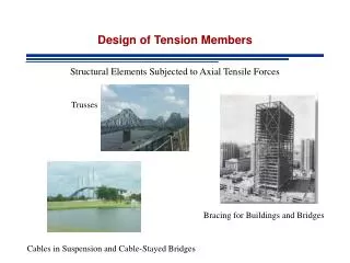
What is Faults in Cables? • When electrical energy is generated in the generations’ stations, it is distributed to the different loads, i.e. cities, towns and villages for consumption then. • The process involves stepping up the voltage to minimize the loss of energy in the form of heat. The stepped up voltage is distributed to grid stations where it is stepped down for distribution to the local transformers where it is finally stepped down and distributed to the consumers. • Distribution of the electrical energy is done via electrical cables. The cables are either insulated or uninsulated.
Types of Cable Faults Open-Circuit Faults: Open circuit fault is a kind of fault that occurs as a result of the conductor breaking or the conductor being pulled out of its joint. In such instances, there will be no flow of current at all as the conductor is broken (conveyor of electric current). Short-circuit or cross fault: This kind of fault occurs when the insulation between two cables or between two multi-core cables gets damaged. In such instances, the current will not flow through the main core which is connected to load but will flow directly from one cable to another or from one core or multi-core cable to the other instead. The load will be short circuited. Ground or earth faults: This kind of faults occurs when the insulation of the cable gets damaged. The current flowing through the faulty cable starts flowing from the core of the cable to earth or the sheath (cable protector) of the cable. Current will not flow through the load then.
Types of Tests to locate faults in cables Blavier Test (For a Single Cable Faults) Loop Test Open Circuit Test Potential Fall Test
Blavier Test (For a Single Cable Faults) • When a ground fault occurs in a single cable and there is no other cables (without faulty one), then blavier test can be performed to locate the fault in a single cable. • In other words, in the absence of a sound cable to locate fault in the cable (to make a loop by connecting both cable as we do in the Murray loop test), then measurement of the resistance from one side or end is called blavier test. • In blavier test, resistance can be measured by two ways. • To insulate the far end of the cable • To ground (earthed) the far end of the cable
Fault to ground resistance = rResistance from the Far end to the cable fault = r1Resistance from the testing end of the cable to the fault = r2
Loop Tests to finding Cable faults • These kinds of tests are carried out on short circuit faults or earth fault in underground cables. • Cable faults can be easily located if a sound cable runs along with the grounded cables. Following are the types of loop tests. • Murray loop Test • Varley loop Test. • Earth Overlap Test
Murray Loop Test • The connection on how a cable faults can be located using Murray loop test method is shown below. • Wheatstone bridge’s principle is used in murray loop test to find the cable faults. • Ra and Rb are the two ratio arms consisting of resistors. G is a galvanometer. The cable having fault (Rx) is connected to the second cable (Sound cable Rc) through low resistance link at the far end. • The Wheatstone bridge is kept in balance by adjusting resistance of the ratio arms Ra and Rb until the galvanometer deflection is zero.
where l = length of a single cable (In meters of yards)2l = total length of two cablesx = distance from the upper side to the fault
Varley Loop Test The only difference between Murray loop test and Varley loop test is that Varley loop test provision is made for measurement of total loop resistance instead obtaining it from the relation
Earth Overlap Test • In earth overlap test, two measurements are performed (instead of one as in Blavier test). The first measurement of resistance is R1 (between Line to ground i.e. from the testing end to the far (earthed) end). • The second measurement of resistance is R2 (between Line to ground i.e. from the far end and the testing (earthed) end).
As in the Blavier test, we also suppose that we know the actual resistance of the cable before the cable fault which is R. R = r1+r2
Open Circuit Test • Open circuit fault can be occurs when cable is pulled out of its joint or a break occurs in the cable. • Such a fault can be traced by carrying out capacity test. • The capacitance of the faulty cable is measured from both ends of the cable either by means of ballistic galvanometer or by bridge method. • Capacitance of the cable to the ground is proportional to the length of the cable.
Potential Fall Test In Potential fall test, Ammeter, voltmeter, Variable resistor (rheostat) and battery are connected as shown below to find the fault location in the cable. This test is carried out with the help of a sound cable that has no fault running along the faulty cable Where V1 and V2 = the voltmeter readings at point A and B;L = length of the faulty core X = length of core between fault and testing end A.
For More Update Please Visit Our Website