Download
1 / 11
110 likes | 118 Views
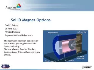
Stellarator magnet options. Electrical/winding issues. Elegant solution for ARIES-AT does not extrapolate well for ARIES-CS High Temperature Superconductor epitaxially deposited on structure Magnet protection for HTS magnets very difficult because of very low speed of propagation of quench

E N D
Electrical/winding issues • Elegant solution for ARIES-AT does not extrapolate well for ARIES-CS • High Temperature Superconductor epitaxially deposited on structure • Magnet protection for HTS magnets very difficult because of very low speed of propagation of quench • Very good mechanical and thermal contact between HTS and structure makes quench energetically impossible (very high temperature/energy margins) • Instead ARIES CS magnet wound in structural semi-continuous cases
Winding for ARIES-CS • Need ductile conductor because of strains required during winding process • Options: • NbTi-like SC • Helias Stellarator design uses NbTi at reduced temperature (2K) • Problem with temperature margin • Wind and react Nb3SN or MgB2 • Need to maintain structural integrity during heat treatment (700 C for a few hundred hours) • No organic material, difficult to use glass.
Issues that need to be addressed for Wind-and-React magnets • Minimization of the conductor size • Ease the winding process • Inorganic insulation, assembled with magnet prior to winding and thus capable to withstand the Nb3Sn heat treatment process. • Two groups (one in the US, the other one in Europe) have developed glass-tape that can withstand the process • The US process uses organic resin/epoxy after heat treatment • The EU process uses all inorganic process
EU process tape (clay/glass, with glass tapes) A. Puigsegur et al., Development Of An Innovative Insulation For Nb3sn Wind And React Coils
The dielectric strength at 4.2 K is ~ 75 kV/mm • similar to traditional insulations with vacuum-impregnated of epoxy resin
Quench protection • To minimize size of conductor for winding, minimize copper in conductor • JCu ~ 200 A/mm2 (200 MA/m2) • Magnet dump < 4 s, preferable ~ 2 s (150 K) • 50 GJ stored energy • 20 kV maximum voltage (0.5 mm thick insulation) • 2 dump circuits per coil • Conductor current ~ 40 kA • Conductor size ~ 3.5 cm2 • Substantially smaller than ITER conductor • Can it be wound inside case?
Consistency • Magnet design • Use Nb3Sn, wind and react • Use 0.5 mm inorganic insulation w/o organic resin/epoxy (20 kV max voltage) • Use 40 kA winding pack current • Use 2 dump-circuits per coil (~50 pairs of current leads) • 0.1 W/kA, ~500 W cooling • Not pretty, but self-consistent • Need to provide costing to system code
Future work • Work with UCSD and ORNL for a better definition of the coil structure • Coil looks wimpy in the outside, very thick in the inside • Bucking vs wedging • Heat loads to coil • Transfer of loads to warm support