Download
1 / 17
180 likes | 323 Views
Heavy Flavor Tracker Overview With parameters pertinent to the PXL Sensor and RDO design . Pixel Sensor and Electronics Group. LBNL Leo Greiner, Howard Matis Thorsten Stezelberger , Xiangming Sun, Michal Szelezniak , Chinh Vu, Howard Wieman UTA Jo Schambach IPHC Strasburg

E N D
Heavy Flavor Tracker Overview With parameters pertinent to the PXL Sensor and RDO design
Pixel Sensor and Electronics Group LBNL Leo Greiner, Howard Matis Thorsten Stezelberger, Xiangming Sun, Michal Szelezniak, Chinh Vu, Howard Wieman UTA Jo Schambach IPHC Strasburg Marc Winter CMOS group
Talk Outline The primarily focus of this talk is technical. Physics and simulations are outside of the scope of the review and discussed only to provide background for requirements. • PXL in HFT - goals and parameters that provide bounds on the sensor and RDO requirements. • PXL environment. • Sensor requirements based on goals and environment. • RDO requirements and design. • Development path for Sensors and RDO. • Summary.
Physics Goals • Direct Topological reconstruction of Charm • Detect charm decays with small c, including D0 K Method: Resolve displaced vertices (100-150 microns)
Inner Detector Region Upgrades TPC – Time Projection Chamber (main detector in STAR) HFT – Heavy Flavor Tracker • SSD – Silicon Strip Detector • IST – Inner Silicon Tracker • PXL – Pixel Detector (PIXEL) Tracking Inward Graded resolution: TPC→SSD → IST → PXL ~1mm ↘ ~300µm ↘ ~250µm ↘ <30µm
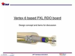
PXL Detector Cabling and cooling infrastructure New beryllium beam pipe (800 µm thick, r = 2 cm) Mechanical support with kinematic mounts 2 layers 10 modules 4 ladders/module Detector extraction at one end of the cone Ladder with 10 MAPS sensors (~ 2×2 cm each)
Tracking Requirements These tracking requirements and all following parameters have been established through simulation studies that have chosen an optimized operating point for the PXL detector through multi-parameter analysis of the entire upgrade system. • -1 ≤ Eta ≤ 1, full Phi coverage (TPC coverage) • ≤ 30 µm DCA pointing resolution required • Two or more layers with a separation of > 5 cm. • Pixel size of ≤30 µm • Radiation length as low as possible but should be ≤ 0.5% / layer (including support structure). The goal is 0.37% / layer • ~200-300 hits / sensor* (4 cm2) in the integration time window (at operating point chosen). * at r=2.5 cm
PXL Tracking Environment Charged particle density (at L = 8 x 1027cm-2s-1) for a 200 µs integration time is: • 63 hits / cm2 at r = 2.5 cm (includes peripheral collision electrons) • 6 hits / cm2 at r = 8.0 cm • Radiation environment: • 20 to 90 kRad and • 2 * 1011 to 1012 1 MeVneq cm-2 year-1
Mechanically Driven Constraints • Detector physical geometry and segmentation. • Sensor power dissipation (air cooling) • Radiation length budget dedicated to cable/sensor assembly (0.17%) • Number of sensors / ladder • Contributes to: • Radiation load (r = 2.5 cm) • Fine twisted pair wire interface to ladders
PXL Sensor Requirements Sensor requirements (consistent with IPHC development direction) • ~2 cm x 2 cm (1 reticle) size. • Pixel size ≤ 30 µm. • Integration time of ≤ 200 µs for L = 8 x 1027cm-2s-1 • Power dissipation ≤ 170 mW/cm2 (air cooling) • Binary output with remote threshold adjustment • Efficiency of ≥ 95% for MIPs with a simultaneous accidental noise rate of ≤ 10-4 • Maintain efficiency and accidental rate after radiation exposure of 90 kRad and 1012 1 MeVneq / cm2. • ≤ 4 LVDS output channels per sensor (ladder space) • Remote configuration
RDO Infrastructure Requirements In addition to the detailed requirements imposed by the interface to the sensors, the RDO system shall: • Triggered detector system fitting into existing STAR infrastructure (Trigger, DAQ, etc.) • Deliver full frame events to STAR DAQ for event building at approximately the same rate as the TPC (1 kHz for DAQ1000). • Have live time characteristics such that the Pixel detector is live whenever the TPC is live. (PXL adds ≤ 5% additional dead time) • Reduce the total data rate of the detector to a manageable level (< TPC rate of ~1MB / event). • Reliable, cost effective, etc. Furthermore, this RDO system will be the basis of sensor testing including production probe testing so additional functionality will be included to enable this system to have the needed additional capabilities.
Sensor generation and RDO attributes ADC CDS Data sparsification readout to DAQ Pixel Sensors CDS Disc. Develop sensor chips, 3 generation program (WBS 1.2.2.2) Complementary detector readout digital signals analog signals digital analog MimoSTAR sensors 4 ms integration time 1 2 Phase-1 sensors 640 μs integration time 3 PXL final sensors (Ultimate) < 200 μs integration time Sensor and RDO Development Path
Summary • The detector parameters presented have been established through simulation studies that have chosen an optimized operating point for the PXL detector through multi-parameter analysis of the entire upgrade system. • This is a set of detector parameters that, when used together, provide the required tracking resolution and efficiency in the required momentum ranges to do the physics to the required sensitivity and in the required time. • We will use these parameters as the basis for the detector design. Deviations will be subject to simulation to determine the effect on performance.
Alternate Technologies Considered • Hybrid • X0 large (1.2%) • Pixel Size large (50 m x 450 m) • Specialized manufacturing - not readily available • CCDs • Limited radiation tolerance • Slow frame rate, pileup issues • Specialized manufacturing • DEPFET • Specialized manufacturing • very aggressive unproven technology MAPS sensors are the technology selected