Download
1 / 66
660 likes | 766 Views
The STAR Heavy Flavor Tracker An Update and Progress Report Jim Thomas Lawrence Berkeley National Laboratory March 6 th , 2012. Lattice results. The Light Quark Program at RHIC is Compelling. Its hot. Spectra. Its dense. Jets & R cp. and it flows at the partonic scale. V n.

E N D
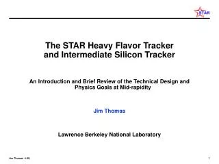
The STAR Heavy Flavor Tracker An Update and Progress Report Jim Thomas Lawrence Berkeley National Laboratory March 6th, 2012
Lattice results The Light Quark Program at RHIC is Compelling Its hot Spectra Its dense Jets & Rcp and it flows at the partonic scale Vn The evidence for a low viscosity, strongly interacting QGP is overwhelming, especially after QM 2011 (v3 , vn wow …!!) and , too!
Where do we go from here? • The Beam Energy Scan has been and will continue to be extraordinarily productive • Alexander Schmah “Elliptic Flow of Identified Particles in Au+Au Reactions at √sNN = 7.7-62.4 GeV” … a tour de force • Heavy Flavor • Elliptic flow for Charm is the smoking gun for thermalization at RHIC • Heavy Flavor energy loss … still a bit mysterious • Clear separation of Charm and Beauty by the topological reconstruction of events will enable a new range of precision
HFT Charm Where does all the Charm go?
Opening the Heavy Flavor Sector • When RHIC turned on … Strange quarks were “heavy and exotic” • We built a Si vertex tracker to locate strange mesons and baryons • This turned out to be too easy to do with the TPC, alone • Kaons, Lambdas, Omegas, Phi and even the Cascade • Cross sections, Flow, Raa and more • Now we want to re-define “heavy and exotic” and go after the Charm quark • Some success already with non-photonic electrons (leptonic and semi-leptonic decays) • Topological reconstruction of open Charm is better. Requires a new high resolution Si detector. • Of course, at the LHC the definition of “heavy and exotic” is quite different. The yield of charmed mesons is greatly enhanced and so they are not exotic. B decays may be “rare and exotic” for ALICE … but maybe not. s can do magical things …. • Note that some success with Upsilon’s at RHIC. Upsilon suppression reported by STAR at QM 2011 using non-photonic electrons.
The HFT – Signature Physics Measurements Charmed Hadron v2 using 200 GeV Au+Au minimum bias collisions (500M events) Charm-quark flow Thermalization of light-quarks • hello Charm-quark does not flow Drag coefficients DOE milestone for 2016: “Measure production rates, high pT spectra, and correlations in heavy-ion collisions at √sNN = 200 GeV for identified hadrons with heavy flavor valence quarks to constrain the mechanism for parton energy loss in the QGP.”
The HFT – Heavy Quark Energy Loss STAR PRL 98 (2007) 192301 and Erratum • Non-photonic electrons decayed from charm and beauty hadrons • At pT ≥ 6 GeV/c, • RAA(n.p.e.) ~ RAA(h±) • A surprising result • Here is what we can do with the HFT using topological ID of open charm RCP
The HFT: The Challenge • Primary Challenges • Neutral particle decay • Proper lifetime, c, 123 m • Find a common vertex away from the primary vertex • Identify daughters, measure pT , and reconstruct the invariant mass The STAR HFT has the capability to reconstruct the displaced vertex of D0 K(B.R 3.8%, c = 123 m) ΛcKp (B. R. 5.0%, c = 59.9 m) and more … Topological Reconstruction of Open Charm
The Heavy Flavor Tracker: Location inside the TPC 4 m • hello TPC PXL IST SSD
The HFT – The configuration SSD 30 IST • The HFT puts 4 layers of Silicon around the vertex • Provides 8 m space point resolution @ 2.5 cm • 30 m vertex resolution @ 1 GeV, 10 m @ 5 GeV • Works at high rate (~ 800 Hz – 1K) • Does topological reconstruction of open charm • Will be ready for the 2014 run Beampipe Pixel Detector 20 10 Centimeters 0 -10 -20 -30
Tracking: Getting a Boost from the TPC OFC • The TPC provides good but not excellent resolution at the vertex and at other intermediate radii ~ 1 mm • The TPC provides an excellent angular constraint on the path of a predicted track segment • This is very powerful. • It gives a parallel beam with the addition of MCS from the IFC • The best thing we can do is to put a pin-hole in front of the parallel beam track from the TPC • This is the goal for the Si trackers: SSD, IST, and PXL • The SSD and IST do not need extreme resolution. Instead, the goal is to maintain the parallel beam and not let it spread out • MCS limited • The PXL does the rest of the work TPC IFC MCS Cone VTX The Gift of the TPC
The performance of the TPC acting alone • The performance of the TPC acting alone depends on the integration time of the PXL chip P(good association) = 1 / (1+S) where S = 2xy Note that the hard work gets done at PXL layer 2. This is a surprise. Single Layer Efficiency Integration Time (sec) The purpose of intermediate tracking layers is to make 55% go up to ~100%
The performance of the TPC + SSD + IST • The performance of the TPC + SSD or TPC + IST acting together depends on the integration time of the PXL chip … but overall the performance is very good P(good association) = 1 / (1+S) where S = 2xy Single Layer Efficiency Integration Time (sec) Random errors only included in hand calculations and in GEANT/ITTF simulations
The HFT – Pixel Technology HFT Si • Unique Features • 20.7 x 20.7 m pixels • 100-200 sec integration time • 436 M pixels • 0.37% X/X0 per layer • Install and Replace in 8 hours • News • Change in process: now using 400 cm moderate Resistivity Si • Depletion voltage ~1V • Better signal to noise and higher radiation tolerance >300 kRad, 1014 n/cm2 • Don’t have to replace the detector every year 22 cm SSD Now using high resistivity Si which allows for a biased depletion region (previously relied upon diffusion to collect the charge) 14 cm IST 8 cm PXL2 2.5 cm PXL1 .
Smart Pixels make the HFT unique High efficiency detector wants high resistivity Si, CMOS cheap, Smart electronics wants low resistivity Si for logic circuits
Exploded view of the HFT inside the TPC HFT SSD IST PXL IFC Inner Field Cage Magnet Return Iron FGT OFC Outer Field Cage TPC Volume Solenoid EAST WEST
The “cone” assembly is removable (annually) Forward GEM Tracker Silicon Strip Detector (IST and HFT underneath) Mechanics and electronics to support the HFT are underneath 4.2 Meters ~ 1 Meter The SSD: 20 ladders located at a radius of 22 cm Double sided Si strips, 95 m pitch, 4 cm long, crossed at 35 mrad The electronics on each end of the ladder are to be upgraded
SSD Electronics • New Ladder Card (left) • Large FPGA on board • Associated RDO in development • Prototypes exist, moving to pre-production phase • Trying to make it all fit Goal: DAQ rate from 200 Hz 1 kHz
Cone Installation Cones installed Fall 2012 Shroud and OSC in place Length ~4 m, Radius ~90 cm SSD will sit on OSC 20 refurbished ladders around the circumference Al mylar wrap covers the region over the SSD and between the shrouds
Exploded view of the HFT inside the TPC HFT SSD IST PXL IFC Inner Field Cage Magnet Return Iron FGT OFC Outer Field Cage TPC Volume Solenoid EAST WEST
Prototype IST Staves (January 2012) 24 Staves at 14 cm radius Intermediate between TPC/SSD and PXL Prototype with Si modules and APV readout chips Wire bonding is a success Readout and electronics very similar to FGT
PXL Requirements and Design Choices • -1 ≤ Eta ≤ 1, full Phi coverage (TPC coverage) • ≤ 30 µm DCA pointing resolution required for 750 MeV/c kaon • Two or more layers with a separation of > 5 cm. • Pixel size of ≤ 30 µm • Radiation length as low as possible but should be ≤ 0.5% / layer (including support structure). The goal is 0.37% / layer • Integration time of < 200 μs • Sensor efficiency ≥ 99% with accidental rate ≤ 10-4. • Survive radiation environment. • Air cooling • Thinned silicon sensors (50 μm thickness) • MAPS (Monolithic Active Pixel Sensor) pixel technology • Sensor power dissipation ~170 mW/cm2 • Sensor integration time < 200 μs (L=8×1027) • Quick extraction and detector replacement (1 day) Requirements Design Choices
Pixel support structure near the vertex 8 cm radius End view Carbon fiber support beams (green) 2.5 cm radius Inner layer Outer layer Two “D” sectors form the heart of the PXL detector. The two halves separate in order to allow for easy access, removal and repair.
Hinge detail pixel support hinges kinematic dock • Parallelogram hinges support the two detector halves while sliding • Cam and follower controls the opening of the hinges during insertion and extraction • Detector support transfers to kinematic dock when positioned at the operating location sliding carriage Reason for no bottom Beam Pipe support… cam followers and linear cam slide rails
Recent Progress – on many different scales • PXL Insertion and Test Bed for installing the PXL detector into STAR • Most Al parts become C fiber in the real thing • A Hallmark of LBL Instrumentation is that things get tested before they are installed • PXL Ladder “Cable” • 2.5 cm by 30 cm • Chips will go on lower 20 cm portion • Prototype in Cu • Final in Al to lower mass of ladder
The PXL Engineering Run (Run 13) • We are planning on a partial installation of PXL ladders for Run 13 • No SSD • No IST • Primarily an engineering run to test the PXL electronics and mechanics • Some physics may be possible • less efficient Joined Patch Mercedes Patch
D0 simulations by Jonathan Bouchet • D0 input • 50k D0 • 0 < pT < 10 • -3 < < 3 • Basic cuts (pT > 0.1, < 1 ) 13K survive • D0 output • Mercedes 970 events • Joined 333 events
Run 13 Engineering Run – Prospects for Physics • D0 acceptance as a function of pT and patch geometry • Overall breakdown and summary of acceptance • Note: this does not include TPC tracking inefficiency nor pT dependent software cuts on the kinematics of the D0 … so the real world will be even more difficult
PXL Detector Characteristics 356 M pixels on ~0.16 m2 of Silicon!
Summary • The HFT will explore the Charm sector at RHIC • We will do direct topological reconstruction of Charm • Our measurements will be unique at RHIC • The key measurements include • V2 • Energy Loss • Charm Spectra, RAA & Rcp • Vector mesons • Angular Correlations • The technology is available on an appropriate schedule
Three STAR Upgrade Projects Finish HFT in time for the 2014 run Finish MTD project by Mar, 2014 and make 80% of the full system ready for year 2014 run HLT is seeking funds but is projected to be under development through FY15, and will be available for physics at all times
Efficiency Calculations in a high hit density environment The probability of associating the right hit with the right track on the first pass through the reconstruction code is: P(good association) = 1 / (1+S) where S = 2xy P(bad association) = (1 – Efficiency) = S / ( 1 + S ) and when S is small P(bad association) 2xy x is the convolution of the detector resolution and the projected track error in the ‘x’ direction, and is the density of hits. The largest errors dominates the sum x = ( 2xp + 2xd ) y = ( 2yp + 2yd ) Asymmetric pointing resolutions are very inefficient … try to avoid it
TPC Pointing at the PXL Detector • The TPC pointing resolution on the outer surface of the PXL Detector is greater than 1 mm … but lets calculate what the TPC can do alone • Assume the new radial location at 8.0 cm for PXL-2, with 9 m detector resolution in each pixel layer and a 200 sec detector • Notice that the pointing resolution on PXL-1 is very good even though the TPC pointing resolution on PXL-2 is not so good • The probability of a good hit association on the first pass • 55% on PXL2 • 95% on PXL1 The purpose of the intermediate tracking layers is to make 55% go up to ~100% All values quoted for mid-rapidity Kaons at 750 MeV/c This is a surprise: The hard work gets done at 8 cm!
Does charm flow hydrodynamically? Heavy Flavor Tracker: unique access to low-pT fully reconstructed charm Are charmed hadrons produced via coalescence? Heavy Flavor Tracker: unique access to charm baryons Would force a significant reinterpretation of non-photonic electron RAA Muon Telescope Detector: precision measurements of J/ψ flow Properties of the sQGP
Rapid Insertion During this operation the PXL box rests on two 6 inch aluminum box beams. These beams are supported independent of walking platform Each half of the PXL detector is supported on two round slide rails both in the PXL storage box and in the MSC. In this procedure the box most be accurately moved into position to align the slide rails of the box with the rails in the MSC Up dated, includes measurement tool for checking alignment of two rail systems and instructions
Calculating the Performance of the Detector • Billoir invented a matrix method for evaluating the performance of a detector system including MCS and dE/dx • NIM 225 (1984) 352. • The ‘Information Matrices’ used by Billoir are the inverse of the more commonly used covariance matrices • thus, ’s are propagated through the system • The calculations can be done by ‘hand’ or by ‘machine’ (with chains) • STAR ITTF ‘machine’ uses a similar method (aka a Kalman Filter) • The ‘hand calculations’ go outside-in • STAR Software goes outside-in and then inside-out, and averages the results, plus follows trees of candidate tracks. It is ‘smart’ software.
Hand Calculations .vs. GEANT & ITTF TPC alone Full System - - - - PXL stand alone configuration Paper Proposal configuration GEANT & ITTF adjusted to have the correct weights on PXL layers Updated configuration … no significant changes in pointing at VTX
Semiperipheral collisions y Coordinate space: initial asymmetry Momentum space: final asymmetry px x Signals early equilibration (teq 0.6 fm/c) Flow: Probing Thermalization of the Medium py
Flow: Constituent Quark Number Scaling In the recombination regime, meson and baryon v2 can be obtained from the quark v2 :
V2 / nq Scaling as a Function of (mT – m0) STAR Preliminary work by Yan Lu • The light quark sector scales beautifully with v2/nq .vs. (mT – m0)/nq • Note that pT < 1 GeV always did scale ! • The strange quark sector also scales with <v2> and the scaling holds at all centralities • Even the meson Does it work in the Charm Sector? A strong test of the theory Yuting Bai, QM 2006 for the STAR Collaboration
Baryons vs. mesons • Coalescence and fragmentation conspire at intermediate pT to give constituent quark number scaling and Baryon-Meson differences. • Coalescence and fragmentation of charm quarks is different than for light quarks … so it is a strong test of the theory • Coalescence of light quarks implies deconfinement and thermalization prior to hadronization • How do baryons and mesons behave in the Charm sector? • The Λc will be a fascinating test … and we might be able to do it with the HFT via Λc / D
“Heavy Flavor” is the next frontier at RHIC • A low viscosity, sQGP is the universally accepted hypothesis • The next step in confirming this hypothesis is the proof of thermalization of the light quarks in RHIC collisions • The key element in proving this assertion is to observe the flow of charm … because charm and beauty are unique in their mass structure • If heavy quarks flow • frequent interactions among all quarks • light quarks (u,d,s) likely to be thermalized Current quark: a bare quark whose mass is due to electroweak symmetry breaking Constituent quark: a bare quark that has been dressed by fluctuations in the QCD sea
Hints of Elliptic Flow with Charm • D e +X • Single electron spectra from PHENIX show hints of elliptic flow • Is it charm or beauty? • The HFT will cut out large photonic backgrounds: • g e+e- • and reduce other large stat. and systematic uncertainties • STAR can make this measurement with 50 M Au+Au events in the HFT • Smoking gun for thermalization at RHIC! Shingo Sakai, QM 2006 for the PHENIX Collaboration Better if we can do direct topological identification of Charm
Heavy Flavor Energy Loss … RAA for Charm • Heavy Flavor energy loss is an unsolved problem • Gluon density ~ 1000 expected from light quark data • Better agreement with the addition of inelastic E loss • Good agreement only if they ignore Beauty … • Beauty dominates single electron spectra above 5 GeV • We can separate the Charm and Beauty by the direct topological identification of Charm Theory from Wicks et al. nucl-th/0512076v2 Where is the contribution from Beauty?
A Rich Physics Program • There is a rich physics program when all of the STAR physics detectors are working together • Flow in the Charm sector • dE/dx in the Charm sector • Recombination and RAA in the Charm sector • Vector Mesons • Charm Angular Correlations • non-photonic electrons • …
The Simplest ‘Simulation’ – basic performance check • Study the last two layers of the system with basic telescope equations with MCS • PXL 1 and PXL 2 alone ( no beam pipe ) • Give them 9 m resolution TPC alone PXL alone • In the critical region for Kaons from D0 decay, 750 MeV to 1 GeV, the PXL single track pointing resolution is predicted to be 20-30 m … which is sufficient to pick out a D0 with c = 125 m • The system (and especially the PXL detector) is operating at the MCS limit • In principle, the full detector can be analyzed 2 layers at a time … hh